What Is Dynamic Positioning (DP)?
Dynamic Positioning is a computer-controlled system used on ships and offshore platforms to automatically maintain a vessel's position and heading using its own propellers and thrusters.
It is essential for operations where anchoring is impractical, such as:
- Deepwater drilling
- Offshore construction
- Diving support
- Cable laying
- Wind farm installation
Core Components of a DP System
- Position Reference Systems — GPS, hydroacoustic beacons, and laser-based systems establish where the vessel is.
- Sensors — Gyros, wind sensors, and motion reference units (MRUs) describe heading and environmental forces.
- Thrusters and Propulsion — Azimuth thrusters, tunnel thrusters, and main propellers generate corrective force.
- DP Control Computer — The brain that processes data and commands the vessel's movement.
DP Training Basics
Training is typically structured around the Nautical Institute's DP Operator Certification Scheme:
- Induction Course — Theory, system components, and basic operations.
- Sea Time — Practical experience on DP-equipped vessels.
- Advanced Course — Complex scenarios, emergency handling, and system failures.
- Final Assessment — Demonstration of competence toward certification as a DP Operator (DPO).
Areas for Training Improvement
- Simulation Technology — Enhance realism and scenario diversity.
- AI and Adaptive Learning — Personalize training paths based on performance.
- Gamification — Make learning engaging and retention-friendly.
- Remote Training — Expand access to high-quality instruction.
- Emergency Scenario Drills — Improve preparation for real-world failures.
Reporting a DP Station Keeping Event
Vessel operators use three categorization levels when reporting a DP station keeping event:
- DP Incident — A major system failure, environmental, or human factor which has resulted in loss of DP capability.
- DP Undesired Event — A system failure, environmental, or human factor which has caused a loss of redundancy and/or compromised DP capability.
- DP Observation — An event that has not resulted in a loss of redundancy or compromised DP operational capability, but is still deemed worthy of sharing.
Sharing these events across the fleet builds the operational knowledge base that keeps every DP vessel on station.
The DNV-ST-0111 Standard: A Unified Assessment
The standard DNV-ST-0111 — Assessment of Station-Keeping Capability of Dynamic Positioning (DP) Vessels provides a straightforward and unified approach to evaluating the station-keeping abilities of DP vessels. Released by DNV in July 2016 after a joint industry effort involving nearly twenty companies from Norway, the Netherlands, and the United Kingdom, it replaced the earlier ERN concept (originally established in 1977) with a verifiable, open industry standard.
Before the standard, the absence of unified calculation methods meant that different input data and approaches produced results that were hard to compare or verify, leading to unfair competition between yards and designers. DNV-ST-0111 addressed this by defining clear methodical requirements for accounting for actuator capacity and environmental forces.
The standard applies to both newbuilds and vessels in service and defines three DP Capability Levels plus two sub-levels for site-specific assessment:
- DP Capability Level 1 — A static, worst-case assessment of the vessel ability to hold position in a defined environmental condition. Supported by a free web app on DNV's Veracity platform.
- DP Capability Level 2 — A more refined static analysis, including post-failure capability, giving transparent operating limits.
- DP Capability Level 3 — Time-domain simulations (using tools such as DNV's DynCap) that capture the vessel's dynamic behaviour in harsh and complex environments, validated against full-scale trials.
The result is consistent, comparable, and verifiable data for risk control, fair competition, and selecting the right vessel for a given weather and operational window.
DP Capability Levels in Detail
The capability levels form a scale: each step represents a significant improvement in DP capability, with the environmental forces typically increasing by more than 50 per cent from one step to the next.
| DP capability level | Description |
|---|---|
| 1 | A prescriptive method for documenting ship-shaped mono-hull vessels using a fixed set of formulas. The calculations are based on the static balance of environmental forces and thrust output. The environmental condition definitions use the Beaufort scale. |
| 2 | A more comprehensive, quasi-static method applicable to all vessel shapes, allowing for project-specific adjustments to calculations. All project-specific data must be documented and justified. Environmental conditions are based on the Beaufort scale. |
| 2-Site | Similar to Level 2, but allowing input of additional, site-specific environmental data and external forces. |
| 3 | Use of time-domain simulations provides enhanced insight into the DP capabilities of a vessel by incorporating dynamic forces into the station-keeping assessment, such as statistics of vessel position and heading, thruster and power utilization and other relevant vessel states. |
| 3-Site | Similar to Level 3, but allowing input of additional, site-specific environmental data and external forces. |
The Level 1 calculation method is fully prescriptive to ensure consistent evaluation of DP capability for verification and benchmarking purposes.
Online Application for Easy Calculation — DP Capability Level 1
In support of the standard, DNV developed the DP Capability Level 1 application, a free web-based tool on the Veracity platform that helps users calculate DP capability results quickly and consistently — lowering the barrier for owners, yards, and charterers to document and compare vessels on the same footing.
Redundancy Groups: Back to Basics
Redundancy is the beating heart of DP — but only if the redundancy groups are truly independent. A redundancy group is a set of interconnected, inter-dependent equipment: power generation, power distribution, auxiliary support systems, thrusters, and related control systems such as DP, PMS, VMS and ESD. Interconnections are best discovered by building redundancy matrixes.
Every DP2 or DP3 vessel needs at least two such groups. In a 2-split design, each group must be self-contained and self-supporting, with enough power, thrusters and support services to control vessel surge, sway and yaw on its own for at least 30 minutes — whether the plant is direct diesel, diesel-electric or pure electric.
FMEA Concept vs. Reality
The FMEA redundancy concept often shows many neat, separate groups (A, B, C, D, E, F). Actual system redundancy analysis usually reveals hidden interconnections — regions where equipment belongs to several groups at once (BC, BE, ABCDE, BCDEF...). The achievable concept then collapses to a few honest groups (BE, ACD, F).
Rule of thumb: be suspicious when you see more than 2 redundancy groups, very suspicious above 3, and unbelieving above 4. The bottom-left design is too expensive; the bottom-right is deceptive — and the deception can be proven by testing.
Test & See
Redundancy groups are independent power, control, support and thrust islands. None can duplicate the full capability of the vessel, but each contributes an independent, verifiable share of it. The classic example is the old workboat 2-split: two main props, two bow and two stern tunnel thrusters, each group holding one of each type, with its own switchboard bus, shaft generator, backup diesel, UPS and DC battery systems, fuel, cooling and hydraulic pumps. Group A may hold slightly better station than Group B simply because its bow thruster sits further from the centre of gravity.
Crossovers need eliminated. The left and right sides of the split must never meet or depend on each other. A standby supply normally isolated at the source is acceptable; feeding one group's control power from the other group's supply is not — a single fault can then kill both groups.
Newer Mistakes
- Combined supplies: "If one supply is good, two must be better." Combining power with diodes caused more blackouts, not fewer. Modern galvanically isolated, current-limited, surge-protected, monitored supplies only help if those protections are regularly tested — group isolation is often cheaper.
- ACOSs (automatic change-over switches): switching thruster servo power to the other distribution board on failure sounds clever, but ACOSs lack basic protection, and a faulted DC drive can drag down both sides. Blackouts increased.
- Common auxiliaries: common or insufficiently protected fuel or seawater cooling is unacceptable. Fuel and cooling are the most vital services — take no shortcuts there.
- Common dual networks: integrated common networks connected previously isolated vital equipment and created common faults still not fully resolved. Intrusive ESD, PMS and master thruster control systems have interfered with, and sometimes endangered, DP redundancy.
Old Testing, Bad Tests, and the Modern 2-Split
Testing on old ships was simple because the systems were simple: kill one main engine, black out group A, verify the backup generators start and connect, run the DC, UPS, fuel and cooling endurance for half an hour while group B keeps position, and prove 100% capacity, fault survival and unimpaired responsiveness of the remaining side. Then repeat the other way.
A bad test leaves hidden truths buried: battery endurance measured while control loads are inactive is no endurance test at all — active loads draw more power. UPS and DC distributions may hide crossovers not shown on drawings, so they must die with their redundancy group during testing, while battery endurance is tested separately. Survival after the fault, and the associated alarms, must be proven.
Modern 2-split testing kills all power in one redundancy group to demonstrate that the remaining group still delivers the thrust, power, capacity and response to keep position — with no unexpected alarms betraying a crossover. Standby pumps are failed in turn with each group; complete loss of group A proves that network B, the DP controllers, and the vessel and power management all honour the redundancy concept.
Based on the original article by Paul Kerr — Engineering Management Professional and Dynamic Positioning Subject Matter Expert (February 2025).
Key Reference: OCIMF DP FMEA Assurance Framework
Dynamic Positioning Failure Mode Effects Analysis Assurance Framework — Risk-based Guidance (First edition, 2020)
- Author / Publisher: Oil Companies International Marine Forum (OCIMF), 29 Queen Anne's Gate, London SW1H 9BU, United Kingdom
This information paper addresses the assurance of DP FMEA quality by prescribing a standardised format for presenting the information behind a vessel's DP redundancy concept — so that an objective and effective assurance process can confirm it. It does not prescribe how to develop an FMEA; it defines what a quality FMEA must show.
Highlights of the guidance:
- Purpose of the FMEA: verify the redundancy design intent, prove redundant equipment groups are independent and fail-safe, identify common points, and develop a proving trials programme to validate the analysis.
- Common failings: inadequate identification of common points, hidden failures and maloperations; FMEAs commissioned too late to influence design; only benign failure modes considered; lessons from incidents not incorporated.
- Common points such as closed bus ties, cross-connected control power and UPS supplies, and some hybrid power designs introduce failure paths that can defeat redundancy — unnecessary ones must be avoided through autonomy, independence and segregation.
- Regulatory basis: IMO MSC.1/Circ. 1580 requires vessels with DP Equipment Classes 2 and 3 to prove their DP redundancy concept through FMEA, including hidden-failure monitoring.
- Standardised presentation: set diagrams for the redundancy concept, Redundancy Verification Tables (RVTs), single failure propagation analysis with FMEA worksheets, and system sketches — with worked examples for power and fuel oil systems.
- Lifecycle assurance: systematic FMEA review throughout the vessel's life, not just the five-yearly refresh, triggered by modifications, new missions, and lessons from DP incidents.
Adherence to the framework is confirmed by OVID inspectors as part of the DP FMEA assurance processes commissioned by OCIMF members chartering DP vessels.
Shell Technical Note: Annual DP Trials — Group Redundancy Tests and Rolling Trials
Annual DP Trials — Group Redundancy Tests and Rolling Trials — Clarification
Official document: Shell Technical Note, 6 November 2023
Reference: GRT_11202306
Author: Suman Muddusetti, Shell Marine Risk Team (MRT)
This technical note clarifies Shell's expectations for Group Redundancy Tests (GRTs) and rolling trials when annual DP trials are submitted for review. Its central requirement is that all elements of performance, protection and detection on which DP single-fault tolerance depends must be proven every year.
What a Group Redundancy Test Must Prove
A GRT is primarily a performance test of the surviving redundancy group, not a failure test of the group that is shut down. The test should simulate the total loss of one complete DP redundancy group and demonstrate that the remaining group or groups can still produce surge, sway and yaw control, maintain position and heading, and do so without relying on equipment from the isolated group.
For the highest level of assurance, the shutdown should include every energy source and distribution within the affected group — including UPS and battery-backed systems. This proves that no concealed crossover is helping the surviving plant. If UPS, battery or other distribution tests are performed separately, the engineering reason must be documented and any resulting assurance gaps must be closed by effective annual validation testing.
Rolling Trials — Shell's Position
IMO MSC 645 and MSC.1/Circ.1580 require annual confirmation that the DP system is in good order. Shell therefore does not support moving critical tests onto a multi-year rolling cycle when they prove performance, protection or detection essential to the vessel's redundancy concept and single-fault tolerance.
Rolling trials may be considered only for non-critical redundancy above that required for single-fault tolerance, supported by competent analysis and clear documentation. A history of reliable operation alone is not proof: on-demand protective and detection functions may remain unexercised until deliberately tested or called upon during a fault.
Thruster Controls and VFDs
Excluding a VFD speed-control-loop failure test from the annual programme is acceptable only when analysis and validation prove that the drive is inherently unable to fail to excess speed or thrust and that no hidden protective function remains untested. This allowance does not extend to azimuth control loops. Emergency stops, thrust magnitude and direction prediction-error alarms, and supporting systems must still be tested annually where single-fault tolerance depends on them.
Test Anxiety Is Not an Exemption
Concern that equipment may fail when control power is restored is not, by itself, justification for omitting required annual testing. Equipment should tolerate loss and restoration of power. Where it does not, operators should identify and correct the underlying causes and manage the test risk rather than leave essential safeguards unproven.
Practical Annual-Trial Standard
- Shut down the complete selected redundancy group, preferably including its stored-energy sources.
- Prove that the surviving group maintains position and heading independently.
- Record the engineering basis for any energy source or distribution left running.
- Test omitted critical distributions separately within the same annual cycle.
- Confirm alarms, indications, emergency stops, protective functions and fail-safe behaviour.
- Reserve rolling tests for demonstrably non-critical redundancy, not essential single-fault-tolerance safeguards.
Primary references cited by the note include IMCA M 190 Rev. 3.1 (August 2023), IMO MSC 645, IMO MSC.1/Circ.1580, and DNV-RP-D102.
MTS Technical Guidance: DP FMEA Gap Analysis
TECHOP_ODP_04_(D)_(FMEA GAP ANALYSIS)
Official document: Technical and Operational Guidance (TECHOP), December 2013
Author / issuing organisation: Dynamic Positioning Committee, Marine Technology Society (MTS)
This guidance addresses the wide variation in the quality and scope of DP FMEAs for vessels entering service or returning after conversion. DP Equipment Class 2 and 3 vessels must demonstrate single-fault tolerance through an FMEA validated by proving trials. A weak analysis can leave single-point and common-cause failures undetected, exposing the vessel to loss of position or heading, injury, environmental damage, infrastructure damage, delay and financial loss.
Purpose of the Gap Analysis
A formal gap analysis checks the scope and methodology of a submitted FMEA against published industry guidance. It is a quality review, not a repetition or correction of the original analysis. The assessment should confirm that the FMEA:
- Was competently executed.
- Covers every DP-related system, including power generation, propulsion and control.
- Considers how the vessel's industrial mission affects its redundancy concept.
- Is effectively validated by DP FMEA proving trials.
- Provides enough information to understand the complete redundancy concept.
Traffic-Light Review Method
| Finding | Meaning |
|---|---|
| Green | Analysis is satisfactory. |
| Yellow | Analysis is incomplete. |
| Red | Analysis is omitted, contains significant errors, or may conceal effects exceeding the worst-case failure design intent. |
| Grey | The issue does not apply to the vessel's design. |
After non-applicable grey entries are removed, the proportion of yellow and red findings gives an indication of the FMEA's overall deficiency. The review distinguishes issues relevant to closed bus ties, open bus ties, DP Class 3, and fail-safe systems that could create a drive-off, including thruster controls, DP controls, position references and sensors.
Best Time to Review
The most useful time for a gap analysis is when the draft FMEA reaches the vessel owner, before submission to Class. At that stage, findings can still influence the design and proving-trials programme. The same review process can also be applied to DP FMEA proving trials and annual DP trials programmes.
Closing the Gaps
- Carry out the gap analysis using the detailed checklist in Appendix A.
- Verify yellow and red findings against the vessel's original design documents.
- Complete additional failure-mode analysis where gaps are confirmed.
- For a newbuild, correct the FMEA, proving-trials programme and, where needed, the vessel systems before entry into service.
- For a vessel already in service, mitigate risk through Design, Operations and People, document the barriers, update the FMEA and ASOG/WSOG where appropriate, and actively manage the measures.
The guidance draws on the MTS DP Vessel Design Philosophy Guidelines Part II, DNV-RP-D102, IMCA M166, IMCA M206 and IMCA Information Note M04/04.
Centre of Gravity vs Centre of Rotation (COG vs COR)
A vessel's Centre of Gravity (COG) is its natural pivot point. The Centre of Rotation (COR) is the point the DP system actually uses to control heading and position. When COR coincides with COG — the ideal intact condition — the vessel can deploy its full surge, sway and yaw capability. When the COR is offset, the vessel is always in a partially degraded state.
The regulatory basis
DNV-RP-E306 and the MTS DP Committee guidance state:
"If an alternate centre of rotation (other than centre of gravity / centre of vessel) is contemplated as a means to undertake the industrial mission, capability plots should be developed for this condition for both intact and post worst case failure scenarios."
Shifting the COR — or the lever to one side — changes the moment the thrusters must overcome, so thruster utilization will be different for the same environmental conditions. Static capability plots are conventionally developed with the COR at the vessel midpoint or COG; an offset COR is not captured in those plots unless specifically modelled.
IMCA DPE 01/25 — "Beware of centre of rotation"
IMCA DPE 01/25 warns that a different centre of rotation than the centre of gravity leads to weakened position keeping. The key principles:
- COR ≠ COG is always a partially degraded state. The vessel cannot match the station-keeping performance it achieves when COR and COG coincide.
- The longer the lever arm between COR and COG, the more difficult it is for the vessel to respond — thrusters must counter the extra rotational moment induced by the offset.
- In the intact case (all thrusters operational, COR = COG) the vessel has 100% of its surge, sway and yaw capability.
- After a worst-case failure (WCF) with COR still at COG, capability drops to 50% — but remains balanced across axes.
- After a worst-case failure with COR offset from COG, capability falls below 50% — the lever arm adds rotational burden that consumes surviving thruster margin.
Illustrated: intact, WCF, and WCF with COR offset
| Condition | Thrusters | COR vs COG | Capability |
|---|---|---|---|
| A — Intact | All live | COR = COG (centre) | 100% surge, sway, yaw |
| B — WCF | Two lost | COR = COG (centre) | 50% surge, sway, yaw |
| C — WCF + COR offset | Two lost | COR ≠ COG (offset) | <50% surge, sway, yaw |
| D — Lever arms | — | Virtual vs real arms | Geometric analysis |
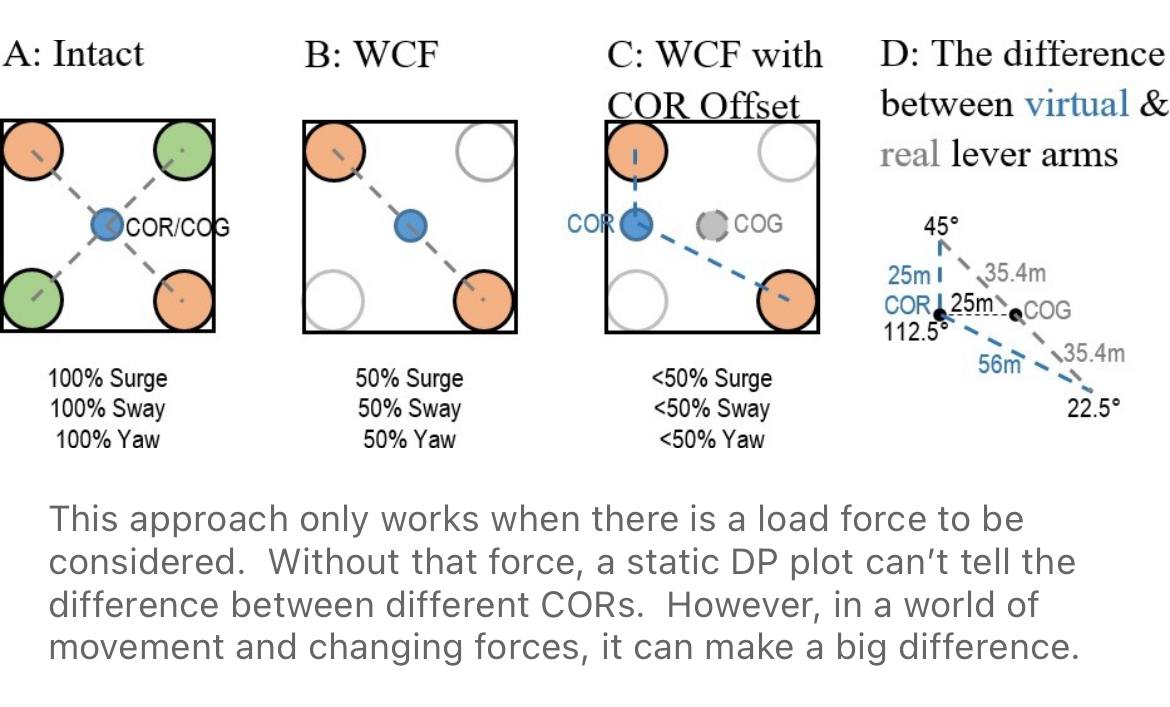
This approach only works when there is a load force to be considered. Without that force, a static DP plot cannot tell the difference between different CORs. However, in a world of movement and changing forces, the choice of COR can make a significant difference to station-keeping performance.
The Six Axes of Freedom — and the Three DP Controls
A floating vessel is free to move in six ways. A DP system actively controls only three of them; the other three it must measure, tolerate and compensate for.
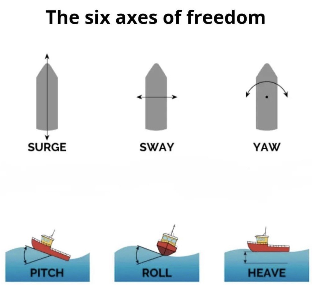
| Axis | Motion | DP role |
|---|---|---|
| Surge | Fore-and-aft translation along the vessel's length | Controlled by main propellers and azimuth thrusters |
| Sway | Athwartships translation | Controlled by tunnel and azimuth thrusters |
| Yaw | Rotation about the vertical axis (heading) | Controlled by differential thrust along the hull |
| Pitch | Rotation about the athwartships axis (bow up / bow down) | Measured, not controlled; corrupts position references if not compensated |
| Roll | Rotation about the longitudinal axis | Measured, not controlled; affects thruster efficiency and crane or gangway work |
| Heave | Vertical translation up and down with the sea | Measured, not controlled; handled by heave compensation on the industrial mission, not by DP |
Surge, sway and yaw are the three horizontal-plane axes the DP control loop closes: measure the offset, calculate the required thrust, correct. Pitch, roll and heave are wave-frequency motions in the vertical plane. Thrusters cannot usefully oppose them, but they must still be known — this is the work of the Motion Reference Unit (MRU) or Vertical Reference Unit, which resolves the roll, pitch and heave of the antennas and hydroacoustic transducers so that the measured position refers to the vessel's reference point and not to a sensor swinging on a mast.
Three axes are held. Three are endured. Ignoring the second three is how good position references start telling lies.
Vessel Shielding: Using the Hull as a Breakwater
Source article: Chris Moncrieff, Vessel shielding effect on waves, does it work? — published on LinkedIn and on the Miros Group site, September 2025. Measurements from client vessels operating in the North Sea.
As waves strike the hull they are partly reflected, partly diffracted and partly transmitted around the vessel, creating a shadow zone on the leeward side where wave height is reduced. Every DPO has felt it. The question the article answers is how much — and the answer is large enough to change an operational decision.
Measured reductions — a subsea construction vessel, North Sea
| Case | Weather side Hs | Sheltered side Hs | Reduction |
|---|---|---|---|
| Low sea state | 1.38 m (starboard) | 0.47 m (port) | 66 % |
| Higher sea state, same vessel days later | 3.42 m (port) | 2.07 m (starboard) | 40 % |
In the first case the sensor traces swapped sides abruptly — too fast to be explained by a shift in wave direction. The crew had deliberately turned the vessel to put the working side, the ROV hangar side, in the lee. Good seamanship, visible in the data.
Why it matters to the DP watch
- A forecast or a wave-rider buoy some distance away would have reported 1.4 m Hs in the first case. Technically correct — and blind to the 0.47 m the work site actually saw. The operational window was there and would have been given away.
- Heading choice is a DP decision with a wave consequence, not only a thruster-utilisation decision. The heading that shelters the working deck may not be the heading that minimises thruster load, and the trade-off has to be made deliberately.
- Shielding calms the working area: ROV launch and recovery, subsea construction, personnel transfer. Against vessel day rates and waiting on weather, the difference between downtime and productive hours is measured in money.
- The effect depends on vessel size and on wavelength relative to the hull. It is real, but it is not a constant to be assumed — it has to be measured on the side that matters, which means wave sensors on both sides rather than one forecast for the whole sea area.
The caution
Shielding reduces wave height on one side. It does not reduce the environmental force the DP system has to balance, and a heading chosen for shelter changes the wind, wave and current angles the thrusters must work against — including, where an offset centre of rotation is in use, the yaw moment demanded. Take the operational gain, but take it with the capability plot in front of you.
The forecast describes the sea area. The vessel describes the work site. When those two disagree, believe the vessel.
DP System Manufacturers — the OEM Landscape
The market for DP systems and their supporting equipment is shared between a handful of full-system OEMs, the position-reference specialists whose sensors feed the DP computer, and the propulsion makers whose thrusters do the physical work. Knowing who builds what matters when specifying a newbuild, planning a retrofit, or tracing where a vessel's redundancy concept begins and ends.
Full DP system OEMs
| Manufacturer | Country | DP system | Link |
|---|---|---|---|
| Kongsberg Gruppen / Kongsberg Maritime | Norway | K-Pos — the market reference, from DP-1 to DP-3 | kongsberg.com |
| ABB Group | Switzerland | ABB Ability Marine — integrated power and DP | new.abb.com/marine |
| GE Power Conversion | US | SeaStream DP and vessel control | gepowerconversion.com |
| Wärtsilä | Finland | DP integrated with NACOS navigation and power management | wartsila.com |
| Rolls-Royce plc | UK | Former Rolls-Royce Marine DP range — the commercial marine business was acquired by Kongsberg Maritime in 2019 | kongsberg.com |
| L3Harris (L3 Harris) | US | DP and integrated platform management for naval and offshore tonnage | l3harris.com |
| Navis Engineering | Finland | NavDP 4000 series — favoured on offshore support and construction vessels | navisengineering.com |
| Marine Technologies LLC | US | BridgeMate DP | marine-technologies.com |
| Praxis Automation Technology | Netherlands | Mega-Guard DP | praxis-automation.com |
| RH Marine | Netherlands | Rhodium DP | rhmarine.com |
| Raytheon Anschütz | Germany | Anschütz DP, integrated with their bridge systems | raytheon-anschuetz.com |
| Japan Radio Company (JRC) | Japan | JRC DP systems, often paired with JRC bridges | jrc.co.jp |
| Alphatron Marine | Netherlands | AlphaPos DP, JRC group's European arm | alphatronmarine.com |
| Royal IHC | Netherlands | DP for dredgers and offshore pipelay vessels, built around their own mission equipment | royalihc.com |
| Norr Systems Pte Ltd | Singapore | Norr P-Class DP, part of a broader vessel-management and power range | norr-systems.equip4ship.com |
| Undheim Systems | Norway | JPOS — compact DP for workboats, fish-farm and service vessels; acquired by HAV Group in 2023 and integrated with Norwegian Electric Systems | havgroup.no |
Model-level reference — DP systems, classes and specifications
| System / model | Maker | DP class | Architecture and notable specifications | Official page |
|---|---|---|---|---|
| K-Pos DP-11 / DP-12 | Kongsberg Maritime | IMO Class 1 (upgradable to Class 2) | Single DP controller unit with one dedicated operator station on a dual high-speed network; DP-11 interfaces propellers, thrusters and rudders directly, DP-12 integrates with K-Chief automation and K-Thrust over dual Ethernet | K-Pos DP single |
| K-Pos DP-21 / DP-22 | Kongsberg Maritime | IMO Class 2 (architecture allows Class 3) | Dual redundant controller units, automatic switch-over to hot standby, fault isolation, dual redundant sensor and PRS interface units; DP-22 integrates with K-Chief and K-Thrust | K-Pos DP dual redundant |
| K-Pos operating modes | Kongsberg Maritime | DP1 / DP2 / DP3 | Joystick, Auto Position, Auto Track and Auto Pilot modes; integrated sensor fusion and thrust allocation for reduced fuel burn | K-Pos DP range |
| ABB Ability Marine Pilot Control (DP function) | ABB | up to and including DP2 | DP is a sub-function of Pilot Control, on the AX Bridge platform or stand-alone; all-speed control from one operator position with joystick and touch screen, hydrodynamic modelling that accounts for vessel speed, no settling time between modes | Marine Pilot Control — DP |
| NACOS Platinum DP | Wärtsilä / NACOS Marine | DP0 / DP1 / DP2 / DP3 | "Star" control network architecture, dual networks for Class 2 and 3, meets IMO MSC/Circ. 645, FMEA support; shares hardware, software and UI with NACOS automation, navigation, power management and thruster control | NACOS DP Platinum |
| Bridge Mate DP 1 | Marine Technologies | Class 1 | Fully distributed concept — single control computer, one operator station, separate I/O units for sensors, PRS, power source and thrusters; independent joystick can be interfaced | Bridge Mate DP |
| Bridge Mate DP 2 / DP 3 | Marine Technologies | Class 2 / 3 | Three control computers with majority voting to reject a failed computer or sensor input, minimum two operator stations, dedicated I/O unit per sensor set, per PRS, per power source and per thruster; Ethernet internal wiring suits retrofit | Bridge Mate DP brochure |
| NavDP4000 series | Navis Engineering | DP1 / DP2 / DP3 | Compact touch-screen system, no stabilisation time before DP operations, thrust-allocation logic for single and multiple actuator faults, fuel-saving mode, voice alerts, selectable centre of rotation, data logger, simulator mode; modular for any thruster and PMS type | NavDP 4000 |
| Mega-Guard DP / JC | Praxis Automation | DP1 / DP2 / DP3 | Positioning accuracy down to 1 dm with high-accuracy PRS; solid-state, 24 VDC hardware throughout; tuning modelled and simulator-tested before shipment so sea trials run to three days; supports Mega-Guard DGPS, HPR and taut-wire PRS; JC is the joystick-only variant | Mega-Guard DP |
| Rhodium DPT | RH Marine | DP with dynamic tracking | Dynamic Positioning and Tracking — sails a predefined line or pattern at very low speed, including anomalous heading; single interface across all speeds, integrated autopilot handing over to bow and stern thrusters, multiple control stations, remote diagnostics; stand-alone or integrated with the Rhodium bridge and PCS | Rhodium DPT |
| Synapsis Intelligent Bridge Control | Raytheon Anschütz | INS platform hosting DP | Type-approved INS to MSC.252(83)/IEC 61924-2; task-oriented multifunction workstations with common heading, position and steering sensors — the platform an Anschütz DP installation sits inside | Synapsis INS |
Position reference, sensors and monitoring
| Manufacturer | Country | Contribution to the DP system | Link |
|---|---|---|---|
| Sonardyne | UK | Hydroacoustic position reference — USBL/LBL beacons and transceivers | sonardyne.com |
| Wärtsilä Guidance Marine | UK | Laser and radar position reference — CyScan, SceneScan, Artemis | guidancemarine.com |
| Moxa Inc. | Taiwan | Industrial networking and computing hardware inside DP and vessel-management cabinets | moxa.com |
| Reygar | UK | BareFLEET remote monitoring, including DP performance and station-keeping analytics | reygar.co.uk |
Model-level reference — position reference sensors
| Sensor / model | Maker | Type | Specifications worth knowing | Official page |
|---|---|---|---|---|
| Ranger 2 USBL | Sonardyne | Hydroacoustic (USBL) | Tracks targets beyond 7,000 m with 1-second updates, multiple targets to 11 km; accuracy 0.04% of slant range when fully optimised; 6G hardware with Wideband 2 signalling; DP feature pack adds inertially-aided acoustics (DP-INS); interfaces with any make of DP system | Ranger 2 USBL |
| CyScan AS | Wärtsilä Guidance Marine | Laser PRS (targets) | Range 10 m to 2,500 m, full 360° scanning, twin laser pulse rate 30 kHz, automatic wave compensation, Absolute Signature target identification, multi-target operation gives relative heading; XT variant for Arctic service | CyScan AS |
| SceneScan | Wärtsilä Guidance Marine | Targetless laser PRS | Range 10 m to 200 m, full 360° scanning, Class 1M laser; positions off the whole scene rather than a discrete target by matching live scans to a learned map — no prisms to rig or maintain; monopole mode for wind-farm SOV work | SceneScan |
| Artemis | Wärtsilä Guidance Marine | Microwave radar PRS | Long-range microwave position reference for platform and FPSO approach work, unaffected by fog, rain and low visibility that degrade laser systems | Guidance Marine products |
| BareFLEET | Reygar | Performance monitoring | Remote vessel monitoring including station-keeping and DP performance analytics — evidence for trials records and post-event review rather than a position reference in its own right | BareFLEET |
Propulsion, thrusters and compact DP
| Manufacturer | Country | Contribution | Link |
|---|---|---|---|
| Thrustmaster of Texas | US | Azimuth and tunnel thrusters, portable dynamic positioning packages | thrustmaster.net |
| Twin Disc | US | Marine transmissions and control systems feeding DP propulsion | twindisc.com |
| Volvo Penta | Sweden | DPS — Dynamic Positioning System for leisure and light commercial craft | volvopenta.com |
| Xenta Systems | Italy | X-DP — joystick-integrated "virtual anchor" DP for yachts | xentas.com |
| Comex | France | Diving and subsea services whose vessels carried early DP installations | comex.fr |
The list above reflects the key players named in the DP system market's current landscape. The deep divide to remember: the full-system OEMs own the control computer and the redundancy philosophy; the reference and sensor makers own the truth about position; the thruster makers own the force. A DP vessel is where all three agree, continuously, about where the ship is allowed to be.
Human Factors: DP Incidents Don't Start with Thrusters — They Start in the Mind
In DP Incidents Don't Start with Thrusters. They Start in the Mind (May 2025), offshore master and DP specialist Rodrigo Carvalho turns the lens away from the machinery and onto the watchkeeper. Despite the robust technological architecture of DP systems, the greatest risks remain human in origin: judgment errors, misread alarms, and underestimated degraded states can compromise an entire operation.
The argument
- The missing layer. DP safety is built on layers — sensor redundancy, segregated power, FMEA (IMCA M 166), annual trials (IMCA M 190). But as IMCA M 103 stresses, no risk structure is complete without accounting for human limitations. The most critical failures reported to IMCA arise during high cognitive-load moments: switching control modes, misinterpreting degraded alarms, misjudging readiness to proceed in the CAM/TAM context.
- Automation bias. Excessive trust in the system — "the computer will take care of it" — is itself a failure mode. Improper gain settings, misuse of biasing, or a misread ASOG have direct impact on positioning integrity. Per IMCA M 220, operational decisions must always weigh mission context, environment and vessel configuration.
- Competence is more than training. IMCA M 117 includes non-technical skills — communication, situational awareness, leadership. Failures often come not from missing procedures but from the inability to adapt procedures to the real scenario. CAMO and ASOG must be internalised as cognitive aids, not merely documented.
Paths to improvement
- Better human-machine interface design (IMCA M 205).
- Realistic failure simulations in continuing professional development training (IMCA M 117 / M 190).
- Regular post-event debriefings with a cognitive-analysis focus, fed by IMCA station keeping event reports.
- Context-aware cognitive checklists — not bare task lists.
Are we preparing people to understand what the system is really telling them?
The conclusion pairs naturally with the reporting scheme earlier in this entry: the Incident, the Undesired Event and the Observation are all system records, but most of them began as a decision — or a hesitation — on the bridge. True innovation in DP will come not only from smarter sensors, but from smarter decisions.
Extended Kalman Filter (EKF) — How a DP System Estimates Vessel Motion
The Extended Kalman Filter (EKF) is introduced to approximate the heading, position, and speed of the ship in each of the three degrees of freedom — surge, sway, and yaw (heading). It also includes algorithms for computing the influences of sea currents and waves. The EKF uses a mathematical model of the ship to closely represent the real vessel motion behaviour and constantly corrects that model.
Inputs and the prediction–correction loop
Ship heading and position deviations are evaluated using gyrocompasses and position reference systems (PRS) as input data to the DP system. These estimates are compared with the predicted measurement data generated by the mathematical model, and the variances are then used to update the model.
  Measurements (gyros, PRS)            Mathematical ship model
           │                              │
           ▼                              ▼
       ┌──────────────────────────────────────────┐
       │            Extended Kalman Filter         │
       │   1. PREDICT  vessel state from model     │
       │   2. COMPARE  predicted vs measured      │
       │   3. CORRECT  weight by uncertainty       │
       └──────────────────────────────────────────┘
           │                              │
           ▼                              ▼
     Best estimate of surge, sway, yaw     Updated ship model
     → fed to the DP controller            (uncertainty reduced over time)
Position reference weighting and "dead reckoning" between fixes
The position reference system computes a deviation for each position reference system in use and places various weightings on their estimates according to each system's individual quality in the absence of position measurements. That is to say that the system can perform positioning for some time without position measurement updates from any position reference systems.
In the EKF, the mathematical ship model reliability and the noise level of the position measurement are the basis for deciding how much to trust each estimate. As time passes, the model uncertainty will be reduced by learning from estimated ship responses.
In a sentence: the EKF fuses a physics-based ship model with noisy real-world measurements, weighting each source by how much it can be trusted — and the longer it runs, the more it learns the vessel's actual response.
Tuning when a reference goes quiet
The method is tuned if, for instance, only one position reference system is active and it has a slow update rate. In this situation the model uncertainty may be increased in the period between measurements, and the ship model will be comprehensively updated with each analysis — so the filter stays honest about what it knows and what it is guessing.
| Situation | Model uncertainty between fixes | Action on each new fix |
|---|---|---|
| Several high-quality PRS, fast updates | Low — measurements trusted | Small correction |
| One PRS, fast updates | Moderate | Balanced correction |
| One PRS, slow updates | Raised — the filter knows it is guessing | Comprehensive update, model re-learns |
| No PRS (temporary) | Grows steadily — "dead reckoning" on the model alone | Model holds station until a fix returns |
Why this matters for the DP watch
- The DP controller never sees truth — it sees an estimate. The EKF is what turns noisy gyro and PRS data into that estimate. Understanding that the estimate carries uncertainty is part of competent DP watchkeeping.
- A position reference that drops out does not instantly lose the vessel. Because the model keeps predicting, the DP system can hold station for a short time on model alone — but the uncertainty grows, and the further from the last fix, the less the estimate is worth.
- Slow or single-sensor periods are when the filter is least honest and most learning. That is precisely when a watchkeeper should be most alert to drift and ready to act.
The Kalman filter is the quiet argument between the model and the sensors — and the DP controller acts on whichever side is winning.
Essential Sensors on a DP Vessel
A DP system is only ever as good as what it can measure. The control computer holds station on the strength of three kinds of truth: where the vessel is (position reference systems), how the vessel is moving (heading and motion sensors), and what the weather is doing (wind sensors). Every one of them feeds the Kalman filter, and the filter — not any single instrument — is what the controller actually believes.
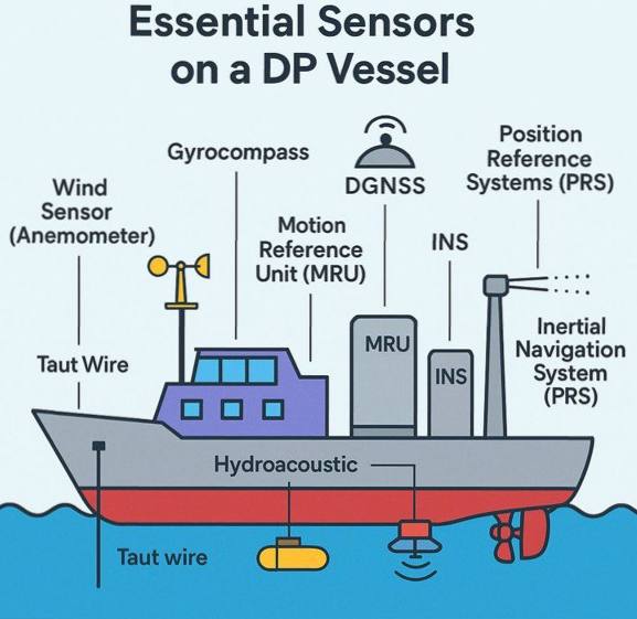
| Sensor | Kind | What it gives the DP system |
|---|---|---|
| DGNSS | Position reference | Absolute position, differentially corrected — the primary surface reference |
| Hydroacoustic (HPR/USBL) | Position reference | Position relative to seabed beacons, independent of satellites |
| Taut wire | Position reference | Position relative to a weighted wire to the seabed — shallow-water work |
| Laser / microwave PRS | Position reference | Range and bearing to a fixed structure (CyScan, SceneScan, Artemis class) |
| Gyrocompass | Motion & heading | True heading — the datum for every heading correction |
| MRU | Motion & heading | Roll, pitch and heave — corrects the position references for vessel motion |
| INS | Motion & heading | Inertial dead reckoning that bridges reference outages |
| Wind sensor (anemometer) | Environment | Wind speed and direction — feed-forward against wind load before position even moves |
The watchkeeping consequence: redundancy of position references is not a luxury. When one reference drops out, the filter leans harder on the vessel model and on the survivors — and a single slow reference raises model uncertainty between every update. An uncompensated MRU or a biased gyro will feed the filter a lie it cannot see, and the controller will faithfully correct toward a wrong heading. Cross-check displayed heading against the compasses and the reference geometry after any sensor changeover.
No single sensor is the truth. The Kalman filter decides who to believe — the watchkeeper decides whether to believe the filter.
DP Drills: Mastering Preparedness — IMCA M273
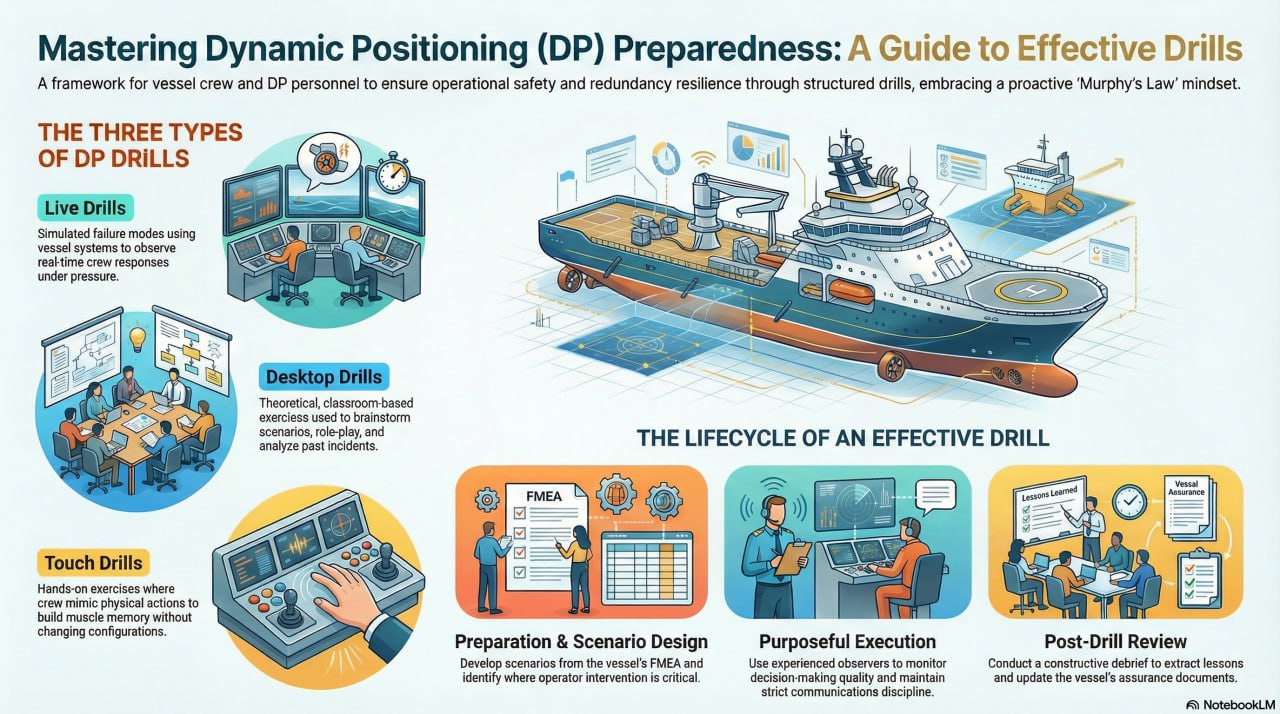
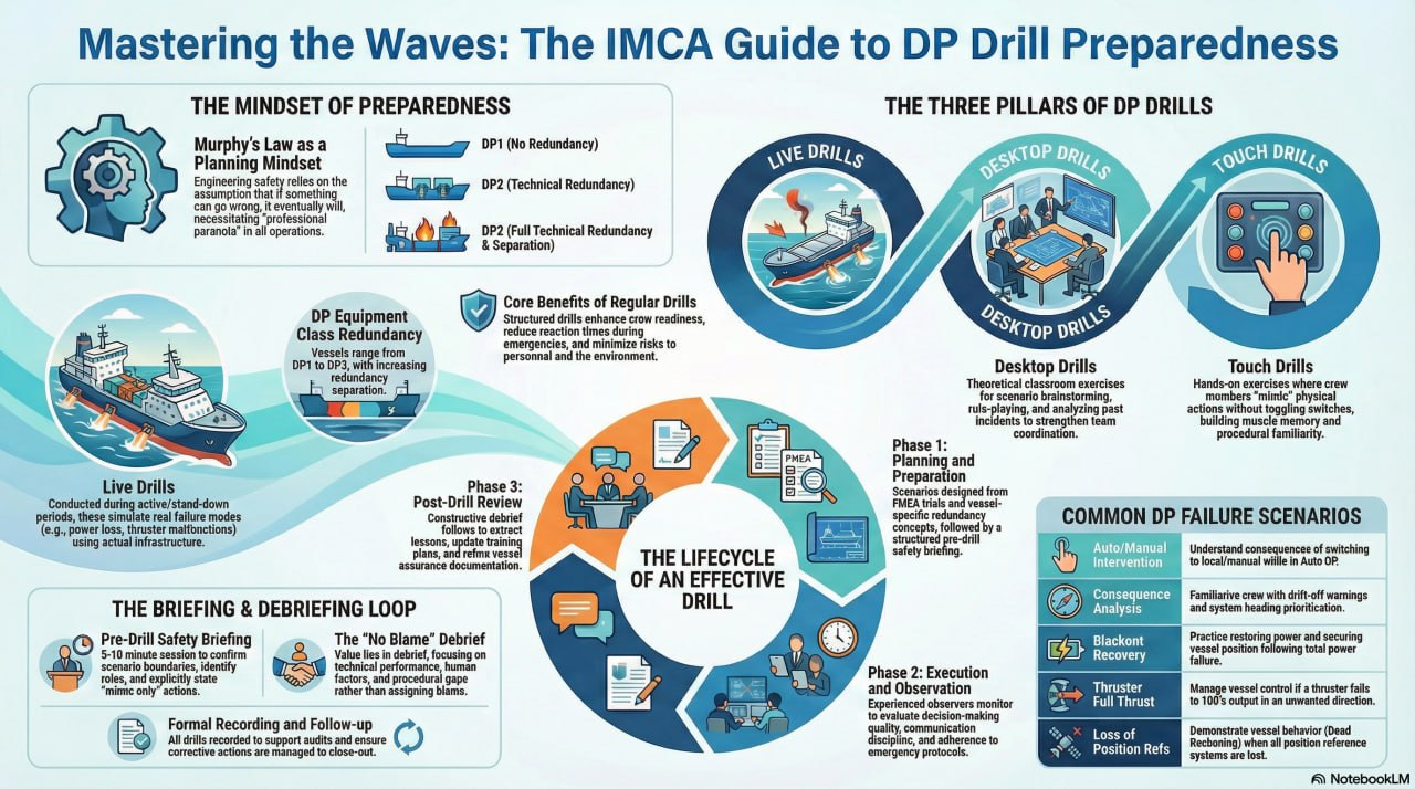
A redundancy concept proves itself on paper and in trials; drills prove the people who must operate it. IMCA M273 — DP Drills: Guidance on the Planning, Conducting and Reviewing of DP Drills provides the operational framework, applicable to Equipment Class 1, 2 and 3 vessels. The guiding mindset: drills are not design validation — they are structured learning opportunities that reinforce the human performance the redundancy concept relies upon.
Download the strategic guide: Mastering DP Preparedness — IMCA M273 (PDF)
The Planning Mindset
"Anything that can go wrong, will go wrong." In DP operations, single-point failures are treated as inevitable, and human error is as likely as hardware failure. An organisation that runs on optimism lets problems creep in; professional paranoia drives robust procedures. IMCA M117 defines the competence standard; IMCA M273 defines the drill method that keeps competence real.
The Three Tiers of Drills
| Tier | Context | Focus | Value |
|---|---|---|---|
| Live drills | Active operations or annual trials | Real failure modes, alarms, environmental forces | Tests the system and the crew response under pressure |
| Desktop drills | Classroom, port calls, pre-mobilisation | Theoretical scenarios, role-playing, past-incident analysis | Builds a shared mental model without risking the vessel |
| Touch drills | Onboard familiarisation | Muscle memory and ergonomics — mimic only, no physical actions | Reinforces physical response sequences |
Live drill scenarios include power-system blackout or bus-tie failure, thruster and position-reference failures, emergency-stop consequences, and sensor spoofing to test anomaly detection. The applied failure alone is not the drill — the true value lies in the realistic human emergency response.
The Five-Phase Cycle
- Plan — design scenarios that target known operator-intervention vulnerabilities: manual fuel changeover on DP3 vessels, manual changeover of a stern tunnel thruster, emergency-stop activation to convert a drive-off into a drift-off.
- Brief — a five-to-ten-minute toolbox talk: scenario, what is real versus simulated versus mimic-only, system status and degraded redundancy, hazards and time to safely terminate, roles, and confirmation that anyone can stop the drill. If the crew does not agree on the boundaries, the drill is dangerous.
- Execute — simulate realistic conditions without compromising safety; an experienced observer records alarms, timings, decision quality and procedure compliance; introduce escalation rather than following a script.
- Debrief — compare expected behaviour from the FMEA against actual crew and system behaviour; examine task fixation, overload, bridge-to-ECR communication, and whether CAM/TAM/ASOG need updating. A learning exercise, not a disciplinary review.
- Record — participants, outcomes, timings and deviations.
Closing the Loop
A drill is only successful if it updates the institutional memory of the vessel: record → analyse → update → train → record again. Failure to update procedures based on drill findings results in repeated risks and a static safety culture.
Preparedness is not a state; it is an activity. Familiarise people with failure modes, shorten the time to handle emergencies, and minimise risk to crew, vessel and environment.
DP Drills in Pictures
Drill Depth Follows Equipment Class
The higher the equipment class, the more the drills must prove. DP1 has no redundancy — drills centre on recognition and safe termination. DP2 carries technical redundancy — drills must show the crew can manage a single fault without loss of position. DP3 adds full technical redundancy with physical separation — drills must also cover compartment-level events such as fire and flooding. Across all classes, regular drills enhance crew readiness, reduce reaction times during emergencies, and minimise risk to personnel and the environment.
The Briefing and Debriefing Loop
- Pre-drill safety briefing — a five-to-ten-minute session to confirm scenario boundaries, identify hazards and roles, and state explicitly which actions are "mimic only".
- The "no blame" debrief — value lies in the debrief: focus on technical performance, human factors and procedural gaps rather than assigning blame.
- Formal recording and follow-up — every drill is recorded to support audits and to ensure corrective actions are managed to close-out.
Common DP Failure Scenarios to Train
| Scenario | What the crew must demonstrate |
|---|---|
| Auto / manual intervention | Understand the consequence of switching to local or manual control while in Auto DP. |
| Consequence analysis | Familiarity with drift-off warnings and system heading prioritisation. |
| Blackout recovery | Practise restoring power and securing the vessel's position following a total power failure. |
| Thruster full thrust | Manage vessel control when a thruster fails to 100% output in an unwanted direction. |
| Loss of position references | Demonstrate vessel behaviour — dead reckoning — when all position reference systems are lost. |
IMCA M 36/05: The Move Beyond the 1991 “Loss of Position” Standard
IMCA M 36/05 (download the protocol-update briefing, PDF) records the revision of IMCA's reporting categories and Station Keeping Incident Forms. Since 1991, IMCA and its predecessor DPVOA collected station keeping data under the “Loss of Position” (LOP) framework — LOP1 (Major) and LOP2 (Minor). The Marine Division Management Committee identified critical limitations in that legacy system: the LOP definitions left too much room for interpretation, and operators were often unsure whether an incident met the threshold for reporting. The goal of the revision is precision — replace ambiguity with clear definitions so that incident reports provide a wider, more accurate range of data for the annual report.
The New Five-Tier Categorization
These categories replace the previous “Loss of Position 1” and “Loss of Position 2” classifications, and must be used in conjunction with the revised IMCA Station Keeping Incident Form:
| # | Category | Alert status | Definition |
|---|---|---|---|
| 1 | DP Incident | Red | Loss of automatic DP control, loss of position, or any event which resulted in — or should have resulted in — a Red Alert status. |
| 2 | DP Undesired Event | Yellow | An unexpected or uncontrolled loss of position or other event which resulted in — or should have resulted in — a Yellow Alert status, without escalating to a full Red Alert system failure. |
| 3 | DP Downtime | Loss of confidence | Position keeping instability or loss of redundancy that does not warrant a Red or Yellow alert, but leads to a stand-down from operational status for investigation, rectification or trials. The vessel is safe, but operations are suspended. |
| 4 | DP Near-Miss | Detrimental effect | An occurrence with a detrimental effect on DP performance, reliability or redundancy which did not escalate to Categories 1–3 — for example a Fanbeam laser “seduced” by a reflective surface other than the intended target, or a crane load interfering with the Artemis line of sight. |
| 5 | DP Hazard Observation | Potential for escalation | Circumstances identified that had the potential to escalate to a Near-Miss or worse — a laser target placed on a busy walkway where crews wear retro-reflective PPE, speed and latitude corrections fed to all gyros from a single DGPS, or the unexpected loss of essential DP components that would have caused an incident had the vessel been on DP. |
Reporting Hierarchy — Which Category Wins?
- Categories 1, 2 and 3 require the full Station Keeping Incident Form; Categories 4 and 5 may be reported by e-mail or short description.
- Incident types 1 and 2 are likely to result in type 3 (downtime) — do not report the downtime separately.
- Always identify the option on the Incident Form that represents the greatest potential for harm.
- New mandatory field: DP hours since the last incident, undesired event or downtime. This data point allows IMCA to calculate reliability metrics and failure rates across the fleet.
Determining Causality
For incident types 1, 2 and 3, the form requires the event to be broken into three distinct phases — initiating event, secondary cause and the resulting consequence. Example: additional thrust demanded by increasing environmental conditions (initiating event) → stoppage of thrusters (secondary cause) → operator error in the recovery. All sections of the form must be completed for these categories.
Action for operators: log in to the IMCA members-only website to download the revised Station Keeping Incident Forms — two versions are available depending on vessel type — together with guidance notes and safety flashes.
Better definitions lead to better data, and better data to safer seas. Report the category with the greatest potential for harm — not the one that reads best.