Fire hoses only work if every joint between hydrant, hose and nozzle mates and seals first time, in the dark, with a crew in breathing apparatus. This lesson uses a shipboard photo of two couplings to show what to look for during routine fire-main and fire-equipment inspections.
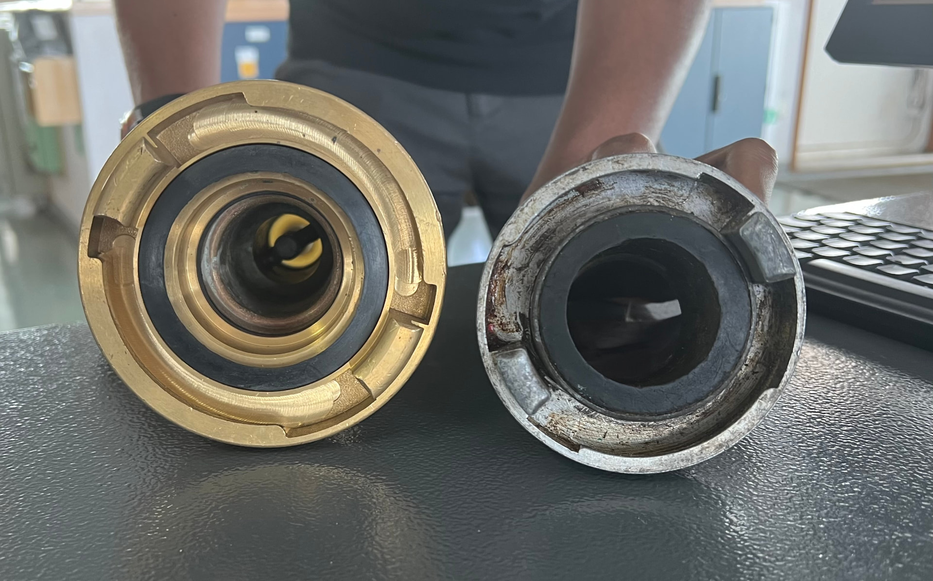
Shipboard photo: a brass claw-type coupling (left) and a worn light-alloy coupling (right). The photo alone does not confirm the coupling standards, sizes or ratings.
What the photo shows
- Left — brass claw-type coupling. Two lugs (claws) and ramps on the face engage a matching coupling with a quarter turn. The face is clean, the lugs are sharp-edged and the rubber seal sits evenly in its groove.
- Right — light-alloy coupling. The lugs are scuffed, the rim shows scoring and reddish-brown staining, and the face is dirty. The seal looks darker and less defined. These are signs to clean, examine closely and, where in doubt, remove from service.
Do not assume two couplings fit just because they look alike. Couplings of different systems, nominal sizes or national standards can look similar but will not lock or seal reliably.
Why couplings matter
SOLAS Chapter II-2 requires fire hoses, nozzles and couplings to be ready for immediate use, and hydrant couplings to be interchangeable on board. Ships that may need a shore connection carry an international shore connection so shore fire services can supply the fire main. Maintenance and inspection are covered by the IMO guidelines in MSC.1/Circ.1432 and the ship's planned maintenance system.
Common coupling types at sea
- Claw / Storz-type (symmetrical). Identical halves lock with a quarter turn. Fast to connect; lugs and seal condition are critical.
- Instantaneous / snap-in. Male and female halves latch on push-in; the latch and spring must work freely.
- Threaded (e.g. NH/NST-type). Screw-together; damaged or cross-threaded threads are a common failure.
The type, size and standard in use are set by the ship's fire-control plan and approved equipment list — check those, not memory.
Standards, sizes and ratings
Full reference: All coupling standards, sizes and pressure ratings
These are the published standards for each coupling type. They do not identify the two couplings in the photo, which have no readable markings; check a coupling's stamped markings and the ship's approved equipment list before relying on any figure.
Claw / Storz-type — DIN 14301–14303 (Germany), EN 14420-8
Sizes are named by a letter, the hose bore and the claw spacing (the distance between the lugs), which decides whether two couplings mate:
| Size | Hose bore | Claw spacing |
|---|---|---|
| D | 25 mm | 31 mm |
| C | 52 mm (C 42 for 42 mm hose) | 66 mm |
| B | 75 mm | 89 mm |
| A | 110 mm | 133 mm |
A C 52 and a C 42 share the same 66 mm claw spacing, so they connect even though the hose bores differ. Couplings of different letters never mate without an approved adapter.
Instantaneous — BS 336 (UK)
Male and female halves push together and latch. The common shipboard size is 2½ in (about 64–65 mm); 1¾ in is also made. BS 336 instantaneous couplings do not mate with Storz-type or threaded couplings.
Threaded — NFPA 1963 NH/NST (USA)
NH (National Hose) threads are named by hose size and thread form, for example 1½ in (1.990 in diameter, 11.5 threads per inch) and 2½ in (3.0686 in, 7.5 threads per inch). Similar-looking threads of other standards will cross-thread or leak.
International shore connection — SOLAS II-2/10 and FSS Code, chapter 2
This is the one coupling with dimensions set internationally, so any port can connect:
| Feature | Requirement |
|---|---|
| Flange outside diameter | 178 mm |
| Flange inside diameter | 64 mm |
| Bolt circle diameter | 132 mm |
| Flange slots | 4 holes, 19 mm diameter, equally spaced, slotted to the flange edge |
| Flange thickness | at least 14.5 mm |
| Bolts and nuts | 4 sets, 16 mm diameter, 50 mm long, plus 8 washers |
| Design pressure | 1.0 N/mm² |
| Material | any suitable for 1.0 N/mm² service |
The ship's side has a coupling that fits its own hydrants or hoses; the flange side faces the shore. Keep it with its gasket, bolts and washers, ready for use.
Pressure ratings
None of the coupling standards above sets one pressure rating for every product. The working and test pressures are marked by the manufacturer or given on its certificate, and must be at least the fire main's maximum pressure. For hoses and couplings on board, use the ratings on the type approval or the manufacturer's data. Test pressures are set by your planned maintenance system and flag-State requirements, not by a figure in this lesson.
Inspection checklist
- Seal (gasket). Present, correctly seated, soft and elastic, with no cuts, cracks, flattening or hardening.
- Lugs, latches and threads. No burrs, bending, heavy wear or cracks; the coupling turns and locks smoothly by hand.
- Body. No cracks, dents, deep scoring or corrosion pitting. Light-alloy couplings are prone to corrosion in salt air; white powder, pitting or staining calls for closer examination.
- Hose binding. The hose is tight on the tail, with no slippage, cuts or leaks at the binding.
- Compatibility. Each hose couples to the hydrants and nozzles it is stowed with. Try it.
- Cleanliness and stowage. Couplings clean, dry and protected; hose stowed so the coupling is ready to connect.
- Record. Log the inspection and any defect in the planned maintenance system.
When to remove from service
Remove a coupling or hose assembly from service and replace it under ship's procedures when:
- the seal is missing, damaged or hardened and cannot be replaced from approved spares;
- the coupling will not lock, locks loosely or leaks under pressure;
- lugs, latches or threads are cracked, bent or worn so engagement is uncertain;
- the body is cracked or badly corroded;
- it is not compatible with the ship's hydrants or nozzles.
Replace a defective item with one of the approved type; do not improvise adapters or tape.
Practical tips
- Carry spare seals of the correct size in each fire station where the system allows.
- Clean and lightly lubricate couplings only with products the manufacturer approves; some greases harm rubber seals.
- Pressure-test hoses and couplings as your planned maintenance system and flag-State requirements specify.
- During drills, have crew actually connect hoses — stiff or mismatched couplings show up immediately.
Lesson from Fremantle Highway (2023): people first
During the July 2023 fire on the car carrier Fremantle Highway off the Netherlands, the Dutch Safety Board found that the shore response concentrated for a long time on fighting the fire rather than rescuing the people on board. Seven crew jumped overboard and were seriously injured, and one died. The other 16 were airlifted off by helicopter, and the shore was not ready to receive them as casualties.
On board, the order of priorities is the same: account for everyone, protect life, and only then fight the fire, using the ship's procedures. Equipment that connects first time, such as hoses and couplings, buys time; it does not replace the decision to evacuate or abandon when the fire cannot be contained.
Source: IIMS News Bulletin, July 2025, summarising the Dutch Safety Board report.
Self-test
- Why should hydrant couplings on board be interchangeable?
Answer 1
So any hose can connect to any hydrant quickly in an emergency. SOLAS II-2 requires interchangeable couplings for this reason.
- What does the international shore connection allow?
Answer 2
It lets a shore fire service supply water into the ship's fire main, even when ship and shore use different coupling types.
- Name three things to check on a coupling seal.
Answer 3
That it is present, correctly seated, and elastic, with no cuts, cracks, flattening or hardening.
- The right-hand coupling in the photo shows scuffed lugs and staining. What should you do?
Answer 4
Clean it and examine it closely. If the lugs, body or seal are damaged, or it will not lock and seal, remove it from service and replace it with an approved item.
- Two couplings look alike. Can you assume they fit?
Answer 5
No. Different standards and sizes can look similar. Check by actually connecting them and follow the ship's approved equipment list.
- Why are light-alloy couplings checked carefully for corrosion?
Answer 6
Light alloys corrode in salt air. Pitting or powdery deposits can weaken the body or lugs and stop the coupling locking.
- Is tape or an improvised adapter acceptable for a leaking coupling?
Answer 7
No. Replace the defective item with one of the approved type under ship's procedures.
- Where should coupling inspections and defects be recorded?
Answer 8
In the ship's planned maintenance system, following company and flag-State requirements.
References
- IMO — SOLAS Chapter II-2, Fire protection, fire detection and fire extinction
- IMO MSC.1/Circ.1432 — Revised guidelines for the maintenance and inspection of fire protection systems and appliances
- IMO FSS Code — International Code for Fire Safety Systems