How a Bow Thruster Works
A bow thruster is a propeller installed in a transverse tunnel near the ship's bow. It produces lateral force when the vessel is stopped or moving very slowly, helping with berthing, unberthing, turning in confined waters and station keeping.
Learning goals
By the end of this lesson you should be able to explain lateral thrust, identify the main components, distinguish controllable-pitch and fixed-pitch arrangements, follow installation and operating precautions, outline maintenance, and explain why effectiveness falls with vessel speed.
Level: introductory · Study time: approximately 45 minutes
The operating principle
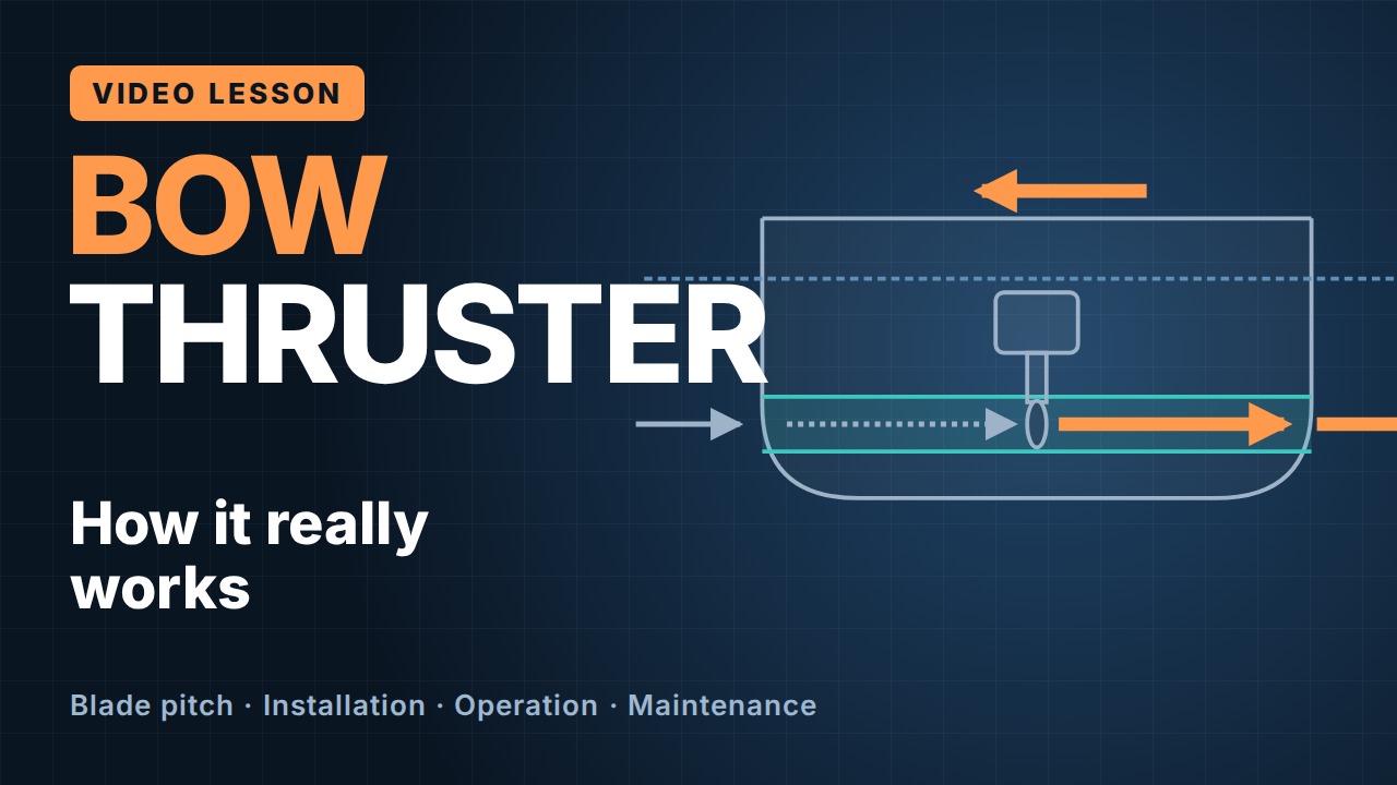
The tunnel propeller draws water from one side of the hull and discharges it as a jet on the other. Newton's third law produces an equal reaction in the opposite direction. If the jet exits to port, the bow moves to starboard; reversing the flow moves the bow to port.
A tunnel thruster is designed around the bollard-pull condition: maximum lateral thrust with the ship stationary. Its tunnel must remain below the lightest operating waterline. The cross-in-a-red-circle marking above each opening warns tugs, small craft and swimmers to keep clear.
Main components and power path
The bridge sends the start, direction and thrust order. Power then passes through the electric motor, elastic coupling, right-angle bevel gearbox, horizontal shaft and tunnel propeller. On a controllable-pitch propeller (CPP) unit, a hydraulic power unit changes blade angle. Optional grid bars protect the opening, but every bar disturbs flow and reduces thrust.
Controllable pitch and fixed pitch
| Arrangement | How thrust changes | How direction reverses |
|---|---|---|
| Controllable pitch (CPP) | Hydraulic oil turns all blades together while the motor normally runs at constant speed | Blade pitch passes through zero and changes sign |
| Fixed pitch (FPP) | A frequency converter changes propeller speed | Propeller rotation reverses |
Inside a CPP hub, oil moves a servo piston and crosshead. Sliding blocks act on crank pins at each blade root, so all blades turn through the same angle. A feedback sensor compares actual pitch with the bridge order.
At zero pitch, the blades slice through the water with little axial force, allowing the motor to start without propeller load. Increasing angle eventually brings flow separation, cavitation and motor-power limits.
Manufacturer limit: approximately 30° from zero pitch is only an order-of-magnitude guide. The permitted angle and load limit for a particular unit must come from its approved manual.
Installation and safe operation
The tunnel must be perpendicular to the centreline and the propeller must not project beyond it. The motor space should be dry, ventilated and accessible, with emergency lighting and a high-bilge-level alarm indicated in the engine control room and on the bridge.
Before starting, confirm the tunnel is submerged; ensure boats, tugs, divers and swimmers are clear; select one control station; start a CPP unit at zero pitch; increase thrust gradually; and remain within rated load. Never store flammable material near the motor.
Maintenance
Routine work includes cleaning, leak and damage checks, lubrication, alarm tests and regular test runs. Drydock work may include blade repair, seal renewal, gear backlash and bearing-clearance checks, crosshead and sliding-block inspection, hydraulic-oil renewal, and pitch calibration.
Limits at speed
A bow thruster is a low-speed tool. As headway increases, flow along the hull bends the transverse jet aft and its useful side force falls sharply. One cited estimate places effectiveness near 20% above five knots, but the actual curve is vessel-specific. An open tunnel also adds resistance at sea; retractable thrusters reduce that penalty when stowed.
Key takeaway
Follow the force: water goes one way and the bow moves the other. Follow the power: bridge order, motor, coupling, gearbox, propeller. Respect submergence, clear openings, approved pitch and load limits, and low vessel speed.