Learning objectives
Identify turnbuckle components, distinguish working load from test load, recognise inspection concerns, and know when to stop and request a competent person's assessment.
A photograph is not a load test or a certificate. This lesson does not approve the pictured arrangement. Follow the vessel's procedures, the actual manufacturer's instructions and applicable flag-state requirements before loading or adjusting rigging.
1. How a turnbuckle works
A turnbuckle is a threaded tension-adjusting device, also called a rigging screw or bottle screw. The photographed item appears to be an open-body jaw–jaw turnbuckle. One end normally has a right-hand thread and the other a left-hand thread. With the end fittings prevented from rotating, turning the body draws them together or moves them apart. Taking up slack does not establish that the working load is safe.
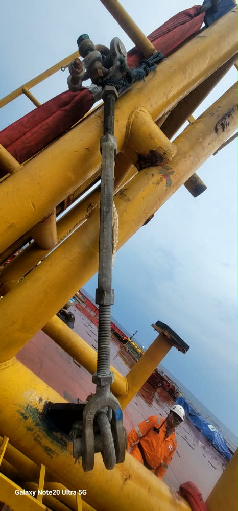
Figure 1 — Overall assembly. Its exact purpose and approved loading arrangement cannot be established from this photograph. All four photographs supplied by Captain Ivan Martsynenko.
| Component | Function | Inspection focus |
|---|---|---|
| Open body | Carries the opposing threads and provides adjustment | Cracks, distortion, severe corrosion, wear and unauthorised heating or repair |
| Threaded stems | Transfer tensile force through engaged threads | Thread damage, corrosion and manufacturer-required engagement at both ends |
| Jaws or clevises | Connect through pins to compatible attachments | Distorted jaws, wear, alignment and pin seating |
| Pins and retainers | Carry load and prevent unintended disconnection | Correct specified pins and approved retention |
| Locking arrangement | Prevents unintended rotation | Manufacturer-specified locknuts or other approved method |
| Rope and connectors | Complete the load path | Rope damage, termination condition and compatibility |
2. Inspect the complete load path
Attachment → connector → pin → jaw → stem → body → opposite stem → jaw → pin → connector → rigging.
Every connection matters. A sound turnbuckle cannot compensate for a damaged rope, unsuitable connector, unretained pin or an attachment not designed for the load. The cited Crosby jaw–jaw turnbuckles are recommended for straight or in-line pull only. This is a product-specific reference, not identification of the photographed maker; verify the actual item's restrictions.
Force should act along the turnbuckle axis. Offset connectors, forced clevises or contact with adjacent steel can introduce bending and side loading. Do not use the body as a lever to force misaligned fittings into place.
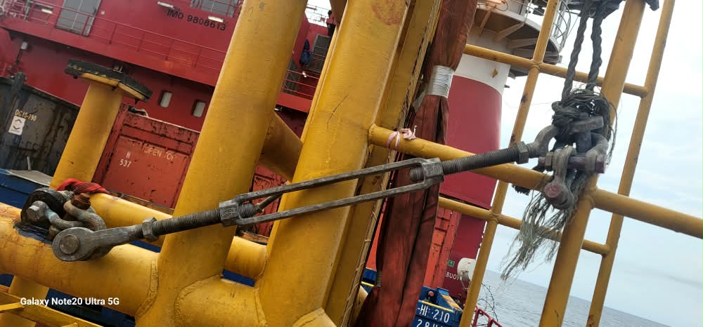
Figure 2 — Inspect the connections, not just the screw. Fraying is visible near the right-hand connection; rope construction, damage severity, loading and intended function cannot be confirmed from this view.
Observations from the photographs
- Fraying: a stop-use concern requiring competent assessment of the rope and termination. Do not confidently identify wire rope versus fibre rope from these views or apply wire-rope broken-wire limits to fibre rope.
- Pins and retainers: some details are obscured. Unknown does not mean absent; inspect both sides of every connection on board.
- Thread engagement: exposed thread does not establish adequate engagement. Verify the exact product's adjustment limits and locking method.
- Steelwork and contact: examine attachments, welds, clearance and corrosion. Paint loss alone does not measure remaining strength.
- Identity: stamps are not reliably readable enough to confirm the complete rating, unit or model. Match the item to traceable documentation.
Immediate action: report concerns, keep personnel clear of the tensioned load path and prevent further use pending assessment. Do not suddenly loosen or disconnect equipment that may be holding a load. Plan safe unloading and isolation with the responsible officer or competent person.
3. Markings and load ratings
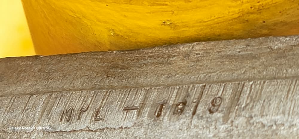
Figure 3 — Worn body stamp. No numerical working load limit is assigned from this photograph.
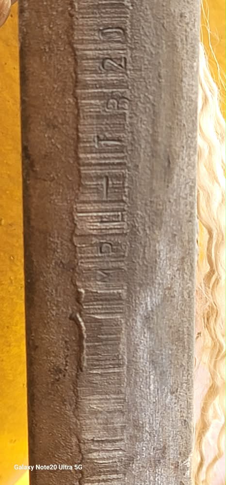
Figure 4 — Additional identification stamp. Verify characters from the physical item and documentation rather than guessing.
| Term | Meaning | Not permission for… |
|---|---|---|
| Working load limit (WLL) | Manufacturer's rated working limit for the identified item under specified conditions | Any direction of loading or any installation |
| Safe working load (SWL) | Permitted working load for a particular application; terminology varies with documentation and jurisdiction | Assuming catalogue WLL automatically applies to every assembly |
| Proof load | Defined test load applied under specified test conditions | Routine operation at the test load |
| Breaking load or strength | Load associated with failure under stated conditions | Treating failure strength as a safe operating target |
A number without a clear unit is not enough: tonnes and kN must not be interchanged. Do not infer capacity from apparent size, a partly readable stamp, a generic safety factor or a neighbouring component. Confirm the actual product rating and the complete assembly's approved application.
Records should identify the item, manufacturer where known, certificate or traceability reference, rating and units, inspection date, findings, inspector and disposition. Missing identity or uncertain rating requires resolution before a rated load-bearing duty.
4. Practical inspection sequence
- Plan and isolate: establish duty, current tension, stored energy and safe access. Arrange controlled unloading where needed; avoid recoil and snap-back paths.
- Confirm identification: match the exact item and configuration to the maker's instructions, certificate and vessel register.
- Clean and examine: use a non-damaging method. Check body, stems and jaws for cracks, deformation, wear, corrosion and unauthorised welding or heating.
- Verify threads: follow the maker's minimum engagement and adjustment limits at both ends. There is no universal acceptable number of exposed threads or engaged turns. Lubricate only as instructed.
- Check pins: verify specified pins, full seating, compatible geometry and approved retention. An improvised bolt or pin is not an approved substitute.
- Check locking and alignment: verify the specified anti-rotation arrangement and a clear axial load path. Do not use improvised locking that damages the equipment.
- Inspect connected rigging: examine rope, termination, connectors and supporting attachments against criteria for the actual construction and service.
- Record and decide: isolate suspect equipment for competent assessment, replacement or authorised repair. Previous successful use is not proof of current fitness.
There is no universal inspection or proof-test interval stated here. Requirements depend on the maker, duty, vessel procedures and applicable law. Lifting, cargo securing and structural tensioning require assessment under the rules for their actual use.
Master's note
A certificate does not cancel a visible defect, and apparently sound metal does not cancel missing traceability. Check both condition and suitability. Never adjust a loaded assembly by trial and error: a small turn can release substantial stored energy.
Why "line of fire" matters
IMCA's 2024 safety statistics found that line-of-fire incidents caused 52% of lost-time injuries among its marine contractor members, more than any other cause. Slips and trips were second at 22%. Line-of-fire injuries happen when a person is in the path of something that moves or releases energy: a load, a parting wire or turnbuckle, a whipping line or a suddenly released tension.
For rigging work this means:
- Before tensioning or releasing a turnbuckle, lashing or wire, work out where it will go if it fails and stand outside that path.
- Never stand in the bight of a line, or under or beside a load while it is lifted or tensioned.
- Release stored tension in a controlled way, and keep hands out of pinch points.
Source: IIMS News Bulletin, July 2025, summarising the IMCA Safety Statistics Report 2024.
Self-test
- How does a turnbuckle adjust length without rotating both connected ends?
Answer 1
Opposite-hand threads allow rotation of the body to draw restrained end fittings inward or move them outward together.
- Can proof load be used as routine working load?
Answer 2
No. Proof load is a defined test load, not a permitted routine load. Use the documented working limit for the equipment and application.
- Can the pictured working load limit be confirmed from these close-ups?
Answer 3
No. Complete marking, unit, maker and identity are not reliably established. Confirm them physically and against traceable documentation.
- What loading direction is recommended for the cited Crosby jaw–jaw turnbuckles?
Answer 4
Straight or in-line pull only. Verify the actual maker's instructions for any other device; side loading introduces bending and may invalidate the intended use.
- What should you do when fraying is visible at a rope connection?
Answer 5
Prevent further use and obtain competent assessment under the correct rope and termination criteria. If tension is present, arrange controlled unloading rather than sudden release.
- How many exposed threads or engaged turns are universally acceptable?
Answer 6
No universal number applies. Verify both ends against the exact manufacturer's engagement and adjustment limits.
- Is an obscured pin retainer proof that no retainer is fitted?
Answer 7
No. Obscured means unknown, not absent. Inspect both sides and verify the specified retention arrangement on board.
- Why not immediately loosen a suspect assembly?
Answer 8
It may hold a load or stored tension. Sudden release can cause recoil, movement or collapse; plan isolation and controlled unloading.
Sources and scope
Source review: 6 November 2026. Original teaching text; photographs supplied by Captain Ivan Martsynenko. General guidance, not certification of the photographed equipment.
- Crosby — Jaw & Jaw Turnbuckles, catalogue page: product-specific ratings and straight/in-line pull recommendation. Reference example, not identification of this maker.
- OSHA 29 CFR 1926.251 — Rigging equipment for material handling: identification, working limits and removal of defective rigging. US construction requirements are cited as safety references, not universal shipboard law.
- OSHA 29 CFR 1926.1413 — Wire rope inspection: wire-rope and end-connection concerns within its crane/derrick scope. Numerical wire-rope criteria must not be applied to unidentified or fibre rope.
Operational decisions require the actual maker's current instructions and the vessel's applicable flag-state, class and safety-management requirements.