Learning objectives
Identify the principal parts of a hydraulic cylinder, recognise stored-energy and handling hazards, explain basic inspection priorities, and understand why overhaul and testing require the exact manufacturer's procedure.
This is an inspection and safety lesson, not a disassembly instruction or approval of the photographed work. The cylinder's maker, duty, pressure rating, dimensions, fault and maintenance outcome are not established from these photographs. Do not imitate the tools or handling arrangements shown without an approved assessment.
1. The shipboard worksite
Hydraulic cylinders turn fluid pressure into linear force. On ships they may operate cranes, davits, hatches and other machinery; the exact function of this photographed cylinder is unconfirmed. The photo sequence appears to show a large cylinder being handled near crane equipment and its rod assembly subsequently withdrawn.
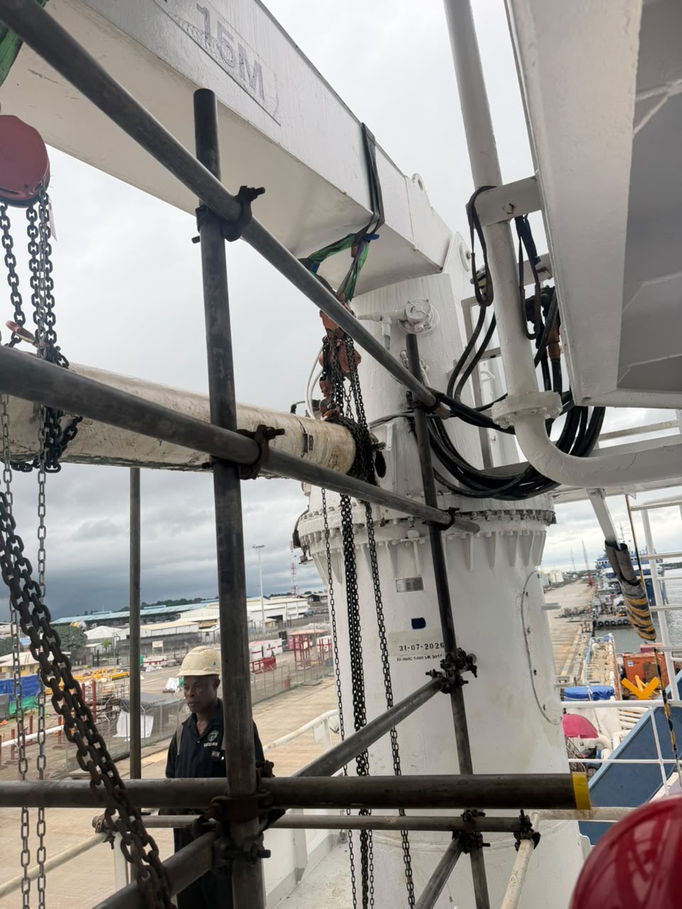
Figure 1 — Access and handling environment. Scaffolding, rigging and hydraulic hoses create separate hazards requiring planning. All photographs supplied by Captain Ivan Martsynenko.
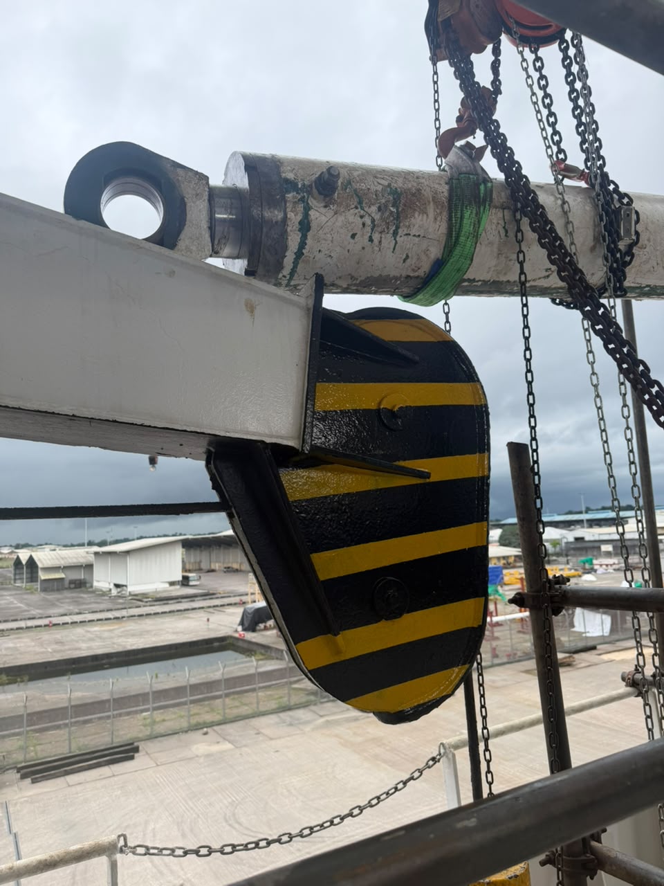
Figure 2 — Handling near the attachment eye. Visible rigging does not establish its rated capacity, attachment approval or load distribution.
2. How the cylinder works
Hydraulic supply → pressure acting on piston area → piston and rod movement → force through the rod-end attachment.
For a basic double-acting cylinder, pressure is directed to either side of the piston. On the rod side, effective area is reduced by the rod cross-section. This is a general explanation: the photographed cylinder's circuit and internal arrangement require its own drawing.
| Part | Typical role | Inspection concern |
|---|---|---|
| Barrel | Contains the piston and pressurised fluid | Bore damage, corrosion, distortion and attachment condition |
| Piston | Separates working chambers and transmits force to the rod | Wear, sealing and secure attachment under OEM criteria |
| Rod | Transfers force outside the cylinder | Scoring, corrosion, straightness and surface condition |
| Gland or rod-guide assembly | Guides the rod and houses sealing elements on many designs | Guide wear, threads, seals and retention |
| Rod seal | Limits fluid leakage along the rod | Damage, compatibility and correct installation |
| Wiper | Helps exclude external contamination at the rod entry | Damage and contamination ingress |
| Piston seal | Limits internal leakage between chambers | Wear or damage; do not confuse it with a rod seal |
| Eye and bush/bearing | Transfers force through the mounting pin | Wear, alignment, pin fit and damage |
A gland, a piston and a seal are different things. Ring-shaped parts are not positively identifiable from shape alone; use the parts drawing and service manual.
3. Isolation before inspection
Stopping the pump is not enough. A raised load, an accumulator, a blocked line or a trapped cylinder chamber can retain energy after shutdown.
- Establish the machinery's duty and secure any supported load with suitable engineered mechanical support. Do not depend on hydraulic pressure alone.
- Follow the vessel's isolation, lockout/tagout and permit arrangements for pumps, controls and other energy sources.
- Account for pressure in both cylinder chambers, lines, load-holding valves and accumulators. Use the specified isolation and depressurisation method.
- Verify the safe state at the relevant points under the approved procedure. One gauge reading zero does not prove every isolated chamber is pressure-free.
- Plan access, lifting and support for the cylinder and rod; assess working-at-height, dropped-object, crush and spill hazards.
Do not loosen a hose fitting, gland or plug as a pressure check. Do not bypass load-holding devices or improvise accumulator discharge.
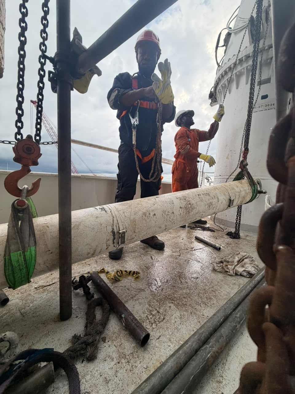
Figure 3 — Team handling. A harness being worn does not establish a suitable attachment, and scaffolding is not automatically a rated lifting anchor. Verify access, fall protection and lifting attachments separately.
Fluid injection: urgent medical assessment
Never search for a hydraulic leak with a hand. Pressurised fluid can enter the body through a tiny opening and cause severe injury. Treat suspected injection as an emergency even when pain or the visible wound seems minor: stop the work, seek urgent medical assessment and provide the fluid identity or safety data when available. Use the approved detection method from a safe position.
4. Rod and gland inspection
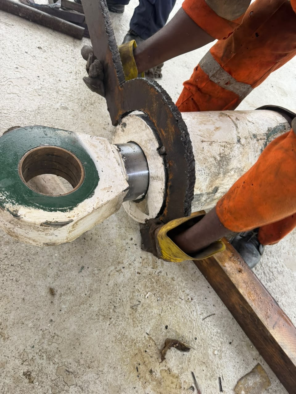
Figure 4 — Rod-entry and gland-area work. This photograph is not an endorsement of tool selection or a guide to applying force.
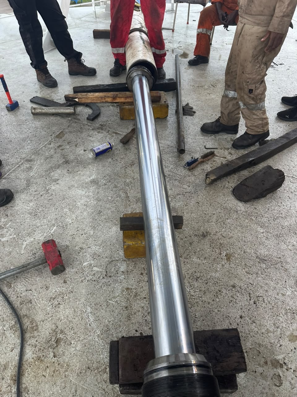
Figure 5 — Withdrawn rod assembly. Support and protect precision surfaces; assess actual suitability of the supports under the maintenance plan.
Inspect the rod for scoring, pitting, corrosion and surface damage. A bright finish in a photograph does not prove acceptable roughness, straightness or dimensions. Examine the barrel bore, guide surfaces, bush/bearing and threads using the OEM methods and limits. Do not infer a crack or a serviceable condition from paint loss alone.
External leakage, internal leakage and load drift can have different causes. Load drift is not automatically proof of a failed piston seal: valves, piping and the circuit also need assessment. Follow the maker's diagnostic procedure.
5. Seals and threaded parts
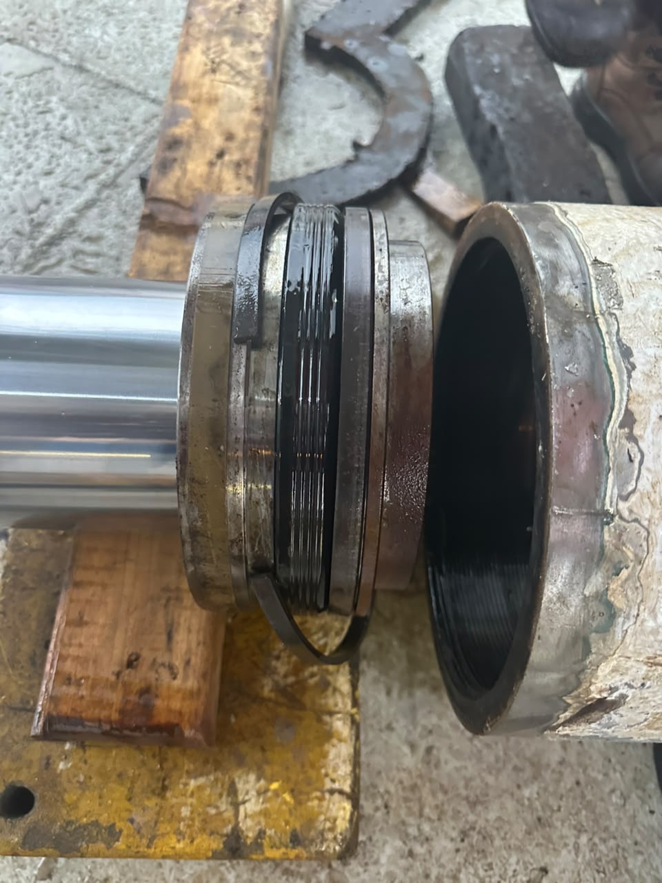
Figure 6 — Sealing-area detail. A loose or displaced ring is visible; its exact type, whether removal was intentional, and failure mechanism cannot be determined from the photo.
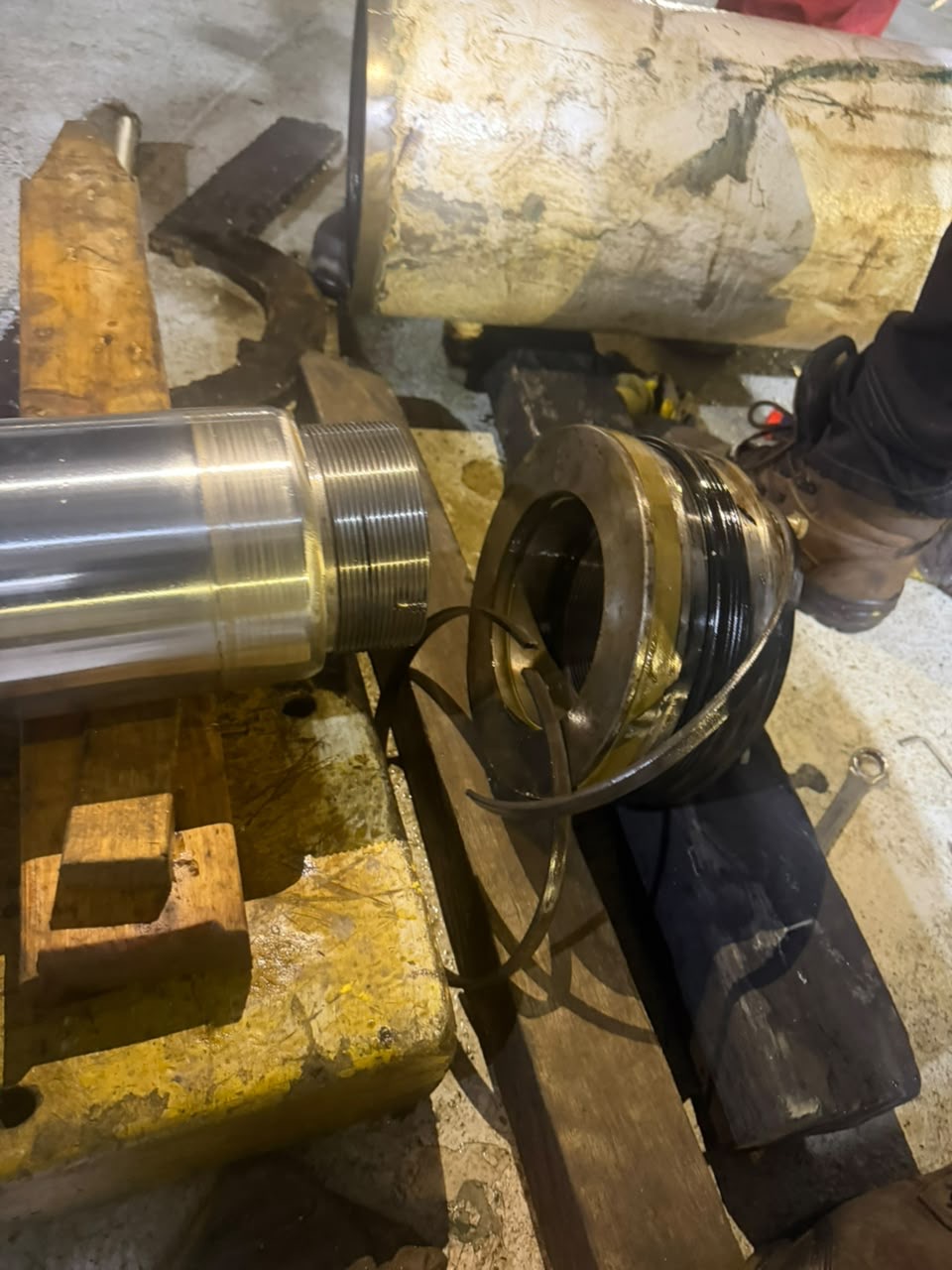
Figure 7 — Separated component. Confirm whether it is a gland or another part from the cylinder drawing; do not label it as a piston solely from appearance.
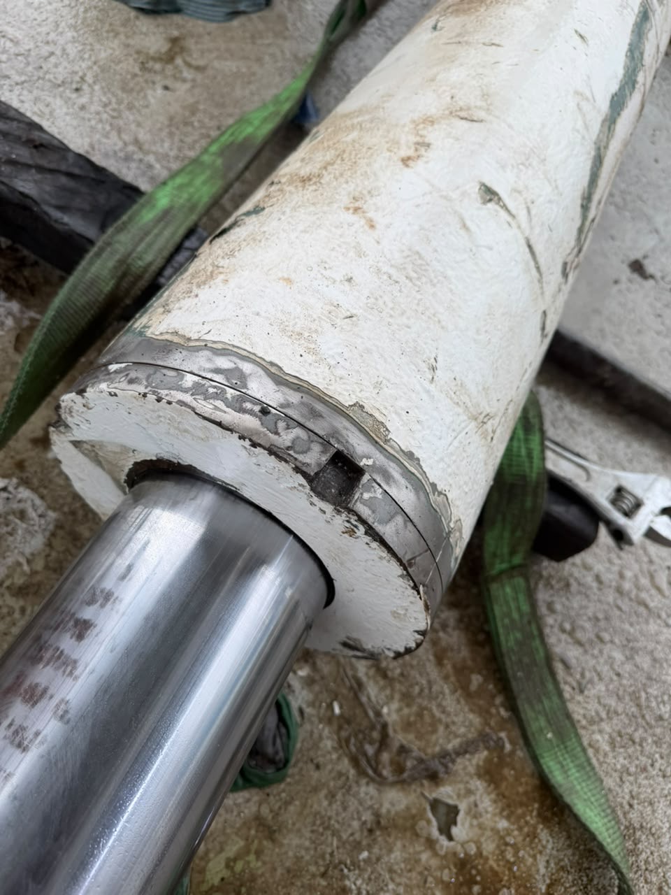
Figure 8 — Rod entry and external condition. Paint condition is not a seal diagnosis or an assessment of remaining strength.
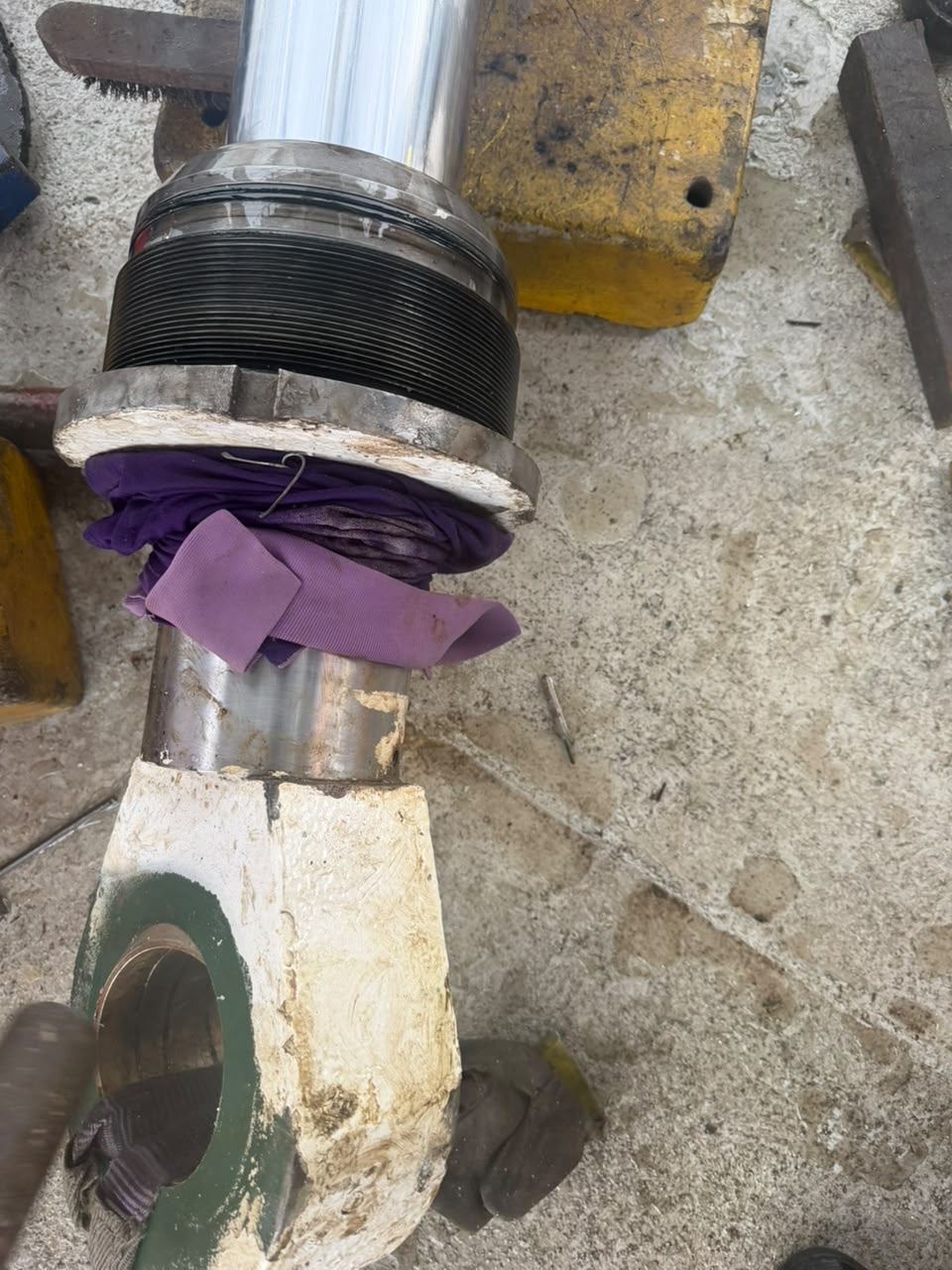
Figure 9 — Threaded component and rod-end area. Required engagement, torque and retention must come from the specific service instructions.
Seal selection must match the specified dimensions, profile, material, fluid, temperature and operating conditions. Similar appearance is not evidence of interchangeability. Confirm orientation, installation sequence, compatible lubricant and any special tools from the OEM. No generic torque, pressure or seal-direction value is supplied here.
Protect threads and sealing surfaces. Do not compensate for damage with unapproved sealant, forced assembly, heating, welding or improvised extensions. Record findings and obtain authorised assessment or replacement.
6. Cleanliness and component handling
Open hydraulic components are vulnerable to contamination. Protect ports promptly with suitable clean closures, work in the specified clean environment, and use lint-free materials and compatible cleaning methods. Loose rags and open storage are not substitutes for an approved cleanliness procedure.
- Support the rod and barrel so they cannot roll, drop or damage precision surfaces.
- Verify lifting points, accessory ratings and the complete load path; prevent side loads on unsupported rods.
- Keep separated parts identified and protected, and document their condition.
- Use only the specified hydraulic fluid and compatible service materials.
- Collect spills and manage waste oil and used seals under vessel procedures.
Read the companion turnbuckle and rigging-inspection lesson for complete-load-path and traceability checks.
7. Controlled return to service
Return to service is not simply reconnecting hoses and starting the pump. Verify parts, documented assembly settings, retention, mountings and connections under the approved procedure. Use the maker's commissioning, air-removal and testing instructions with guards, exclusion zones and the required instrumentation.
Inspect for external leaks without touching pressurised lines; confirm prescribed movement, load-holding and functional checks. Test conditions and loads must be approved for the actual equipment. Do not adopt catalogue proof pressures or generic overload factors as a shipboard test recipe.
Record the work, parts used, measurements, test conditions, findings and authorisation to return the machinery to service. If its duty requires competent examination or certification, complete that requirement before operation.
Master's note
Two different safe states matter: the hydraulic system must be isolated, and the machinery or load must be mechanically secure. Neither proves the other. A stopped pump, an attractive rod surface or a newly fitted seal does not establish safe operation.
Self-test
- Does stopping the pump remove every hydraulic and mechanical hazard?
Answer 1
No. Trapped pressure, accumulators, loaded cylinder chambers and gravity loads may remain. Isolate, verify depressurisation and secure loads under the approved procedure.
- Why must a supported load be mechanically secured before cylinder work?
Answer 2
Hydraulic pressure or valves alone cannot be relied on as maintenance support. Suitable mechanical support prevents movement when hydraulic energy is removed.
- May a fitting be loosened to check for trapped pressure?
Answer 3
No. Use the specified isolation and pressure-verification method. Loosening a fitting can release hazardous fluid or cause movement.
- What is the response to suspected hydraulic-fluid injection?
Answer 4
Treat it as an emergency and seek urgent medical assessment, even for a tiny wound. Never use a hand to find a pressurised leak.
- Are rod seals, piston seals and wipers interchangeable?
Answer 5
No. They perform different functions. Confirm each component and seal specification from the parts drawing and service manual.
- Does the shiny rod in a photo prove it is serviceable?
Answer 6
No. Surface defects, dimensions and straightness require inspection against OEM limits; a photograph cannot certify them.
- Does load drift always prove a defective piston seal?
Answer 7
No. Valves and the hydraulic circuit can also contribute. Diagnose using the actual equipment procedure.
- Can a scaffold tube be assumed to be a lifting anchor?
Answer 8
No. Verify an approved rated attachment and complete load path. Access scaffolding is not automatically suitable for suspended machinery loads.
- Can a seal be selected by matching its appearance to the old one?
Answer 9
No. Verify dimensions, profile, material and operating compatibility against the maker's specification, including required orientation and installation method.
- What governs return-to-service test pressure and loads?
Answer 10
The actual manufacturer's instructions and approved vessel test procedure. No generic pressure or overload factor applies to every cylinder.
Official sources and scope
Source review: 6 November 2026. Original teaching text; photographs supplied by Captain Ivan Martsynenko. These sources provide general safety principles and product-specific examples, not identification or approval of the pictured cylinder.
- UK MCA — MGN 248: Safety preparations prior to machinery maintenance: machinery isolation and shipboard maintenance preparation; read alongside current vessel and flag-state requirements.
- UK HSE — Hydraulic injection injury safety alert: injection hazards and urgent medical attention.
- Parker — Cylinder service assemblies and seal kits bulletin: manufacturer-specific service and sealing guidance, not instructions for the photographed equipment.
Operational maintenance requires the exact cylinder and machinery manuals, competent personnel and applicable vessel procedures.