Learning objectives
Recognise the main features of a wind turbine installation vessel (WTIV), follow the installation cycle, distinguish afloat positioning from seabed-supported jack-up operations, and explain key lifting and geotechnical hazards.
These photographs illustrate the work, not an approved operating procedure. Vessel identity, location, project, cargo weights, crane ratings and operating limits are not established here. Use the vessel manuals, site assessment, lift plans and authorised procedures for actual operations.
1. What the photographs show
Wind turbine installation vessels transport and lift large turbine components offshore. Many are self-propelled jack-ups with deck cargo space, a heavy-lift crane and legs that can support an elevated hull. Other vessel types also support wind-farm construction; not every offshore wind vessel is a jack-up.
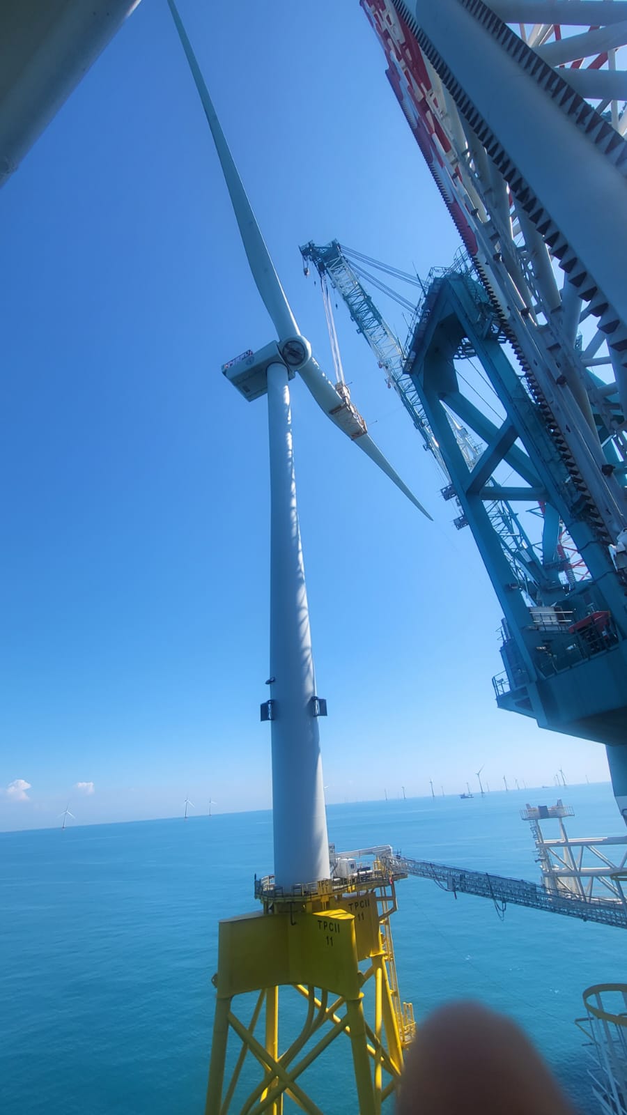
Figure 1 — Close offshore view of a turbine, yellow support structure and nearby installation equipment. Visible proximity does not establish that a lift is underway. All photographs supplied by Captain Ivan Martsynenko.
| Visible feature | General role | What cannot be inferred from the photo |
|---|---|---|
| Tall lattice legs and racks | Guide and support jacking loads | Leg capacity, seabed penetration or approved water depth |
| Large crane | Handle turbine components under a lift plan | Safe capacity at the working radius or allowable wind |
| Cylindrical tower sections | Form the turbine tower when assembled | Weight, centre of gravity or securing adequacy |
| Nacelles and hubs | House drivetrain/generator equipment and connect the rotor | Exact model, rating or installation method |
| Blades and transport frames | Carry long aerodynamic components | Approved lifting points or transport acceleration limits |
2. Port loading and deck preparation
The load-out port supplies components and supports heavy-lift preparation. Towers may be transported upright or in other approved arrangements; blades require purpose-designed supports. The photographs show one arrangement, not a universal loading pattern.
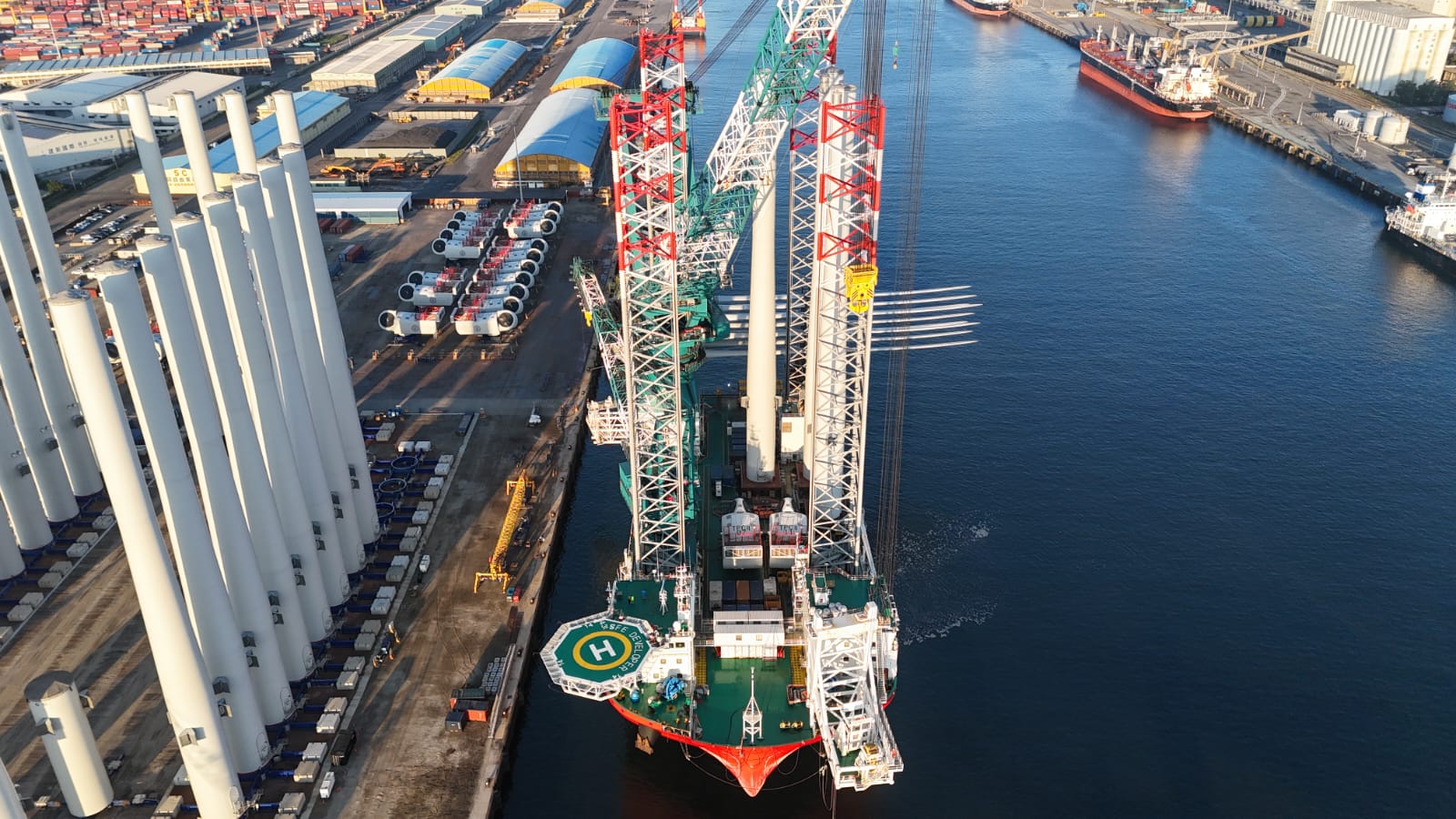
Figure 2 — Port-side view of the vessel and component staging area. A loading port must support the project's lifting, storage and marine-access arrangements.
Before sailing, responsible teams verify the cargo list, component masses and centres of gravity, deck loads, stability, crane configuration and voyage securing. Supports and sea fastenings must suit the expected transport loads, not just the cargo's static weight. Access routes, lifesaving appliances and emergency arrangements must remain usable.
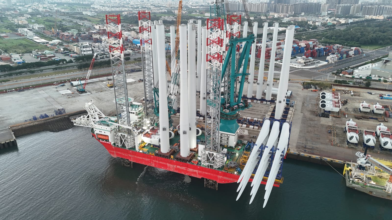
Figure 3 — Tower sections, nacelles and blades staged on the vessel. Their arrangement illustrates the challenge of combining large cargo, crane access and safe deck working space.
Load-out questions
- Are component identity, weight and centre of gravity confirmed in the approved documentation?
- Are deck supports, local deck loading and sea fastenings approved for this voyage?
- Is the crane in its required transit configuration, with clearances and securing checked?
- Are crew routes, emergency access and exclusion zones maintained?
- Are port draft, under-keel clearance, berth and departure constraints addressed?
3. Installation cycle
Port load-out → afloat transit → site positioning → leg touchdown and preload → hull elevation → component lifts → controlled lowering and leg recovery → next location or port.
This is a teaching sequence only. The exact sequence, hold points and allocation of responsibility depend on the vessel, site and project.
| Phase | Principal support or control | Key concern |
|---|---|---|
| Transit | Hull buoyancy and propulsion | Stability, secured cargo, draft and weather route |
| Afloat positioning | Propulsion, and DP where fitted and approved | Position, heading, clearance and operating limits |
| Leg touchdown and preload | Legs, jacking system and seabed interaction | Soil response, uneven penetration and load distribution |
| Elevated installation | Legs and seabed support carry the hull | Approved elevation, structural loads and lift conditions |
| Departure | Planned lowering, refloating and leg recovery | Buoyancy transition, seabed resistance and clearance |
4. Why jack up the hull?
An afloat vessel moves in waves. Raising a jack-up hull above the water can provide a more stable working platform for installation, but replaces an afloat problem with structural and geotechnical requirements. The legs transfer load to the seabed through their feet, often called spudcans on designs equipped with them. Foot design varies and is not identifiable from these photographs.
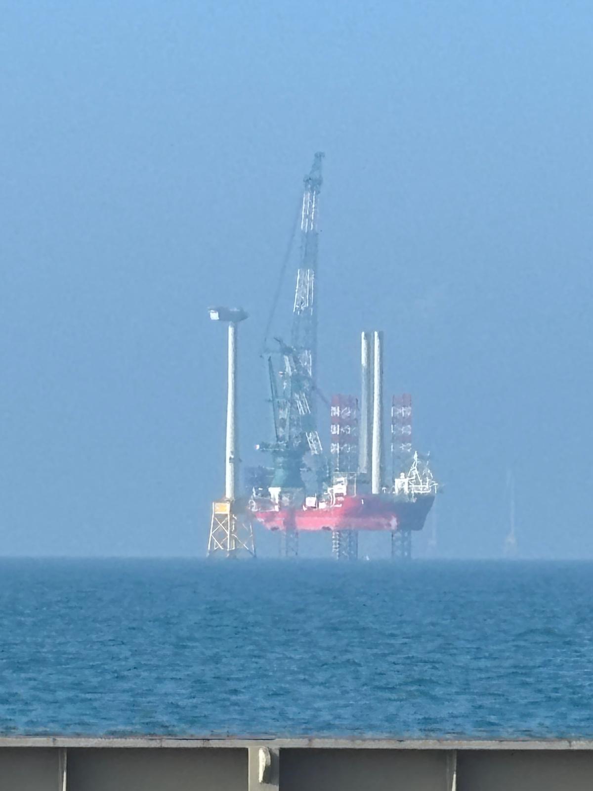
Figure 4 — A distant worksite view. A photograph cannot establish leg loads, preload completion, the measured air gap or fitness for the forecast conditions.
Preload
Preload deliberately applies specified loads to the legs to assess seabed response and settlement before relying on that support for subsequent operations. It is performed under the vessel's approved procedure and site assessment. Different leg counts and designs use different methods; loading diagonally opposed legs is an example for some four-leg designs, not a universal instruction.
Punch-through
Punch-through is a potentially sudden increase in leg penetration or loss of support associated with seabed conditions, for example when a stronger layer overlies weaker material. It can cause uneven support and severe consequences. Site-specific soil information and engineering assessment are essential; a view of a calm sea cannot demonstrate seabed suitability.
Air gap
Air gap is the clearance between the elevated hull underside and the sea surface. Required elevation must account for the approved environmental conditions, including water level and waves. A larger elevation is not automatically safer: leg length, structural capacity and the approved operating envelope also constrain the operation. No universal air-gap value is assigned here.
5. Heavy-lift and weather limits
Crane capacity is configuration-specific. The permitted lift depends on the actual load, radius, boom configuration, rigging and applicable operating limits. A maximum headline capacity is not the permissible load at every radius.
Blades have a large exposed area and can be sensitive to wind. Gusts, component orientation and control of the suspended load matter as well as mean wind speed. Use the lift-specific criteria and authorised forecast sources; do not apply a generic wind-speed threshold to every turbine lift.
- Confirm approved lifting points, lifting tools, rigging certificates and component mass.
- Establish exclusion zones and protect personnel from suspended loads and crush points.
- Verify communications between crane operator, lifting supervisor, deck team and relevant control stations.
- Monitor weather and the applicable stop criteria throughout the operation.
- Plan contingencies, safe landing or securing of a load, and emergency response before starting.
6. DP and jack-up support are different
Dynamic positioning, where fitted, uses propulsion to maintain position and heading while afloat. It may support approach or positioning within the approved operating arrangement. Not all installation vessels have the same DP equipment or class.
Once the hull is elevated on its legs, the legs, jacking system and seabed provide support. DP is not what holds an elevated jack-up hull in place. Follow the vessel procedure for transitions between afloat positioning, leg contact, preloading and elevated operations; do not improvise thruster use during these transitions.
Read the companion lessons on Dynamic Positioning fundamentals and turnbuckles and rigging inspection.
7. Blade racks and spreader lifting arrangements
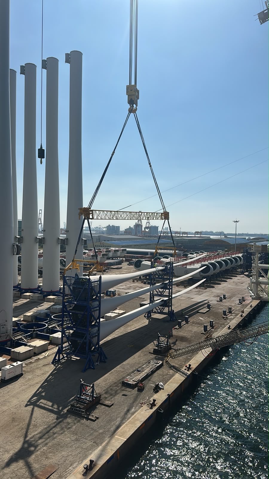
Figure 5 — Blade-handling arrangement. The photograph does not establish the approved lifted unit, capacity or load distribution. All additional photographs supplied by Captain Ivan Martsynenko.
A spreader can maintain separation between sling connections and provide the required lifting geometry. Spreader beams and lifting beams are not interchangeable names for every tool: actual design determines the load path.
Do not assume a transport rack is approved for lifting with the blade inside it. Verify whether the authorised lifted unit is a blade, a rack or both, and use the prescribed tool, attachment points and rigging. Confirm the mass of the complete suspended assembly, including accessories where required by the crane load calculation.
Sling angles affect forces in the legs and tool. Unequal lengths or an offset centre of gravity can redistribute loads; a symmetrical appearance does not prove equal sharing.
- Verify tool identity, capacity, inspection and required testing records.
- Check approved sling geometry, connectors and blade support/contact points.
- Follow the lift plan's load-control method and weather limits; do not improvise tag-line use.
- Maintain exclusion zones and keep personnel clear of suspended loads.
8. Tower loading: lift, land and secure
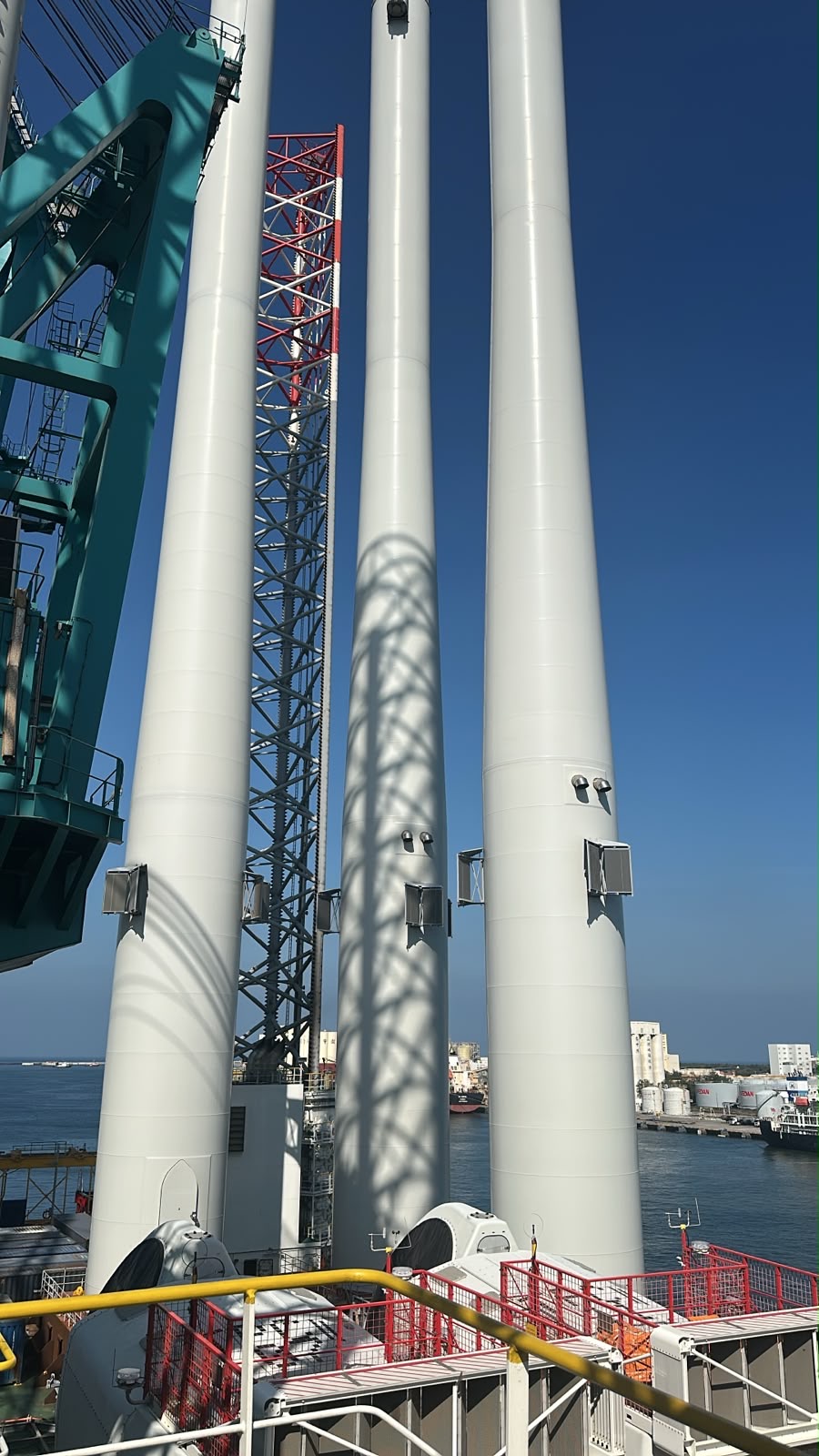
Figure 6 — Upright tower stowage. Position alone does not establish stability, deck capacity or securing approval.
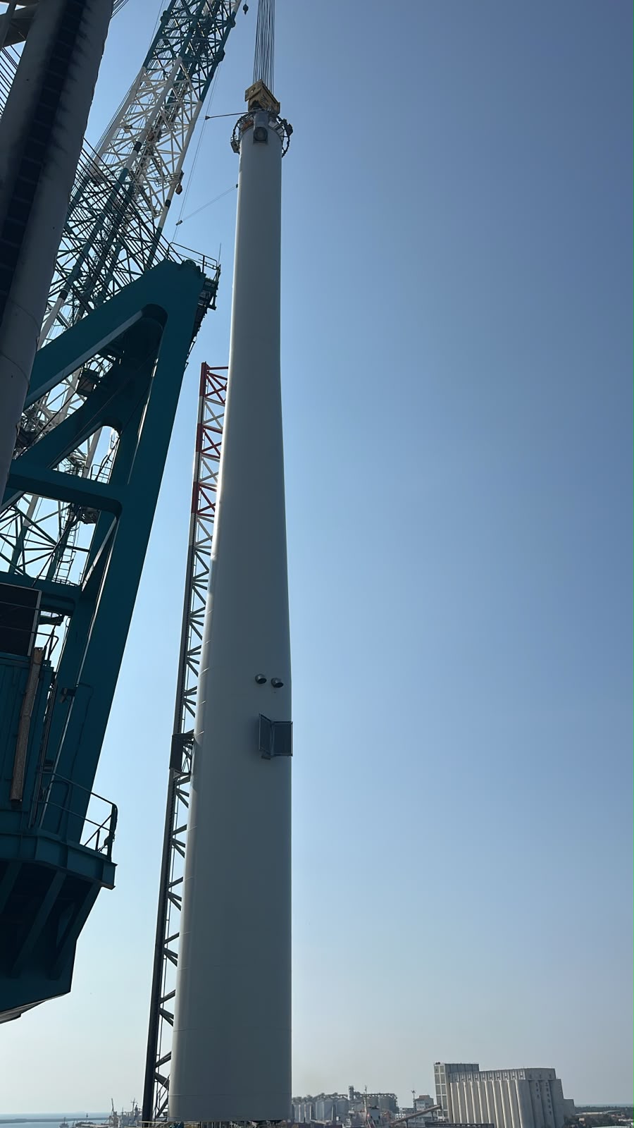
Figure 7 — Tower lifting interface. Exact attachment method and capacity require the approved documentation.
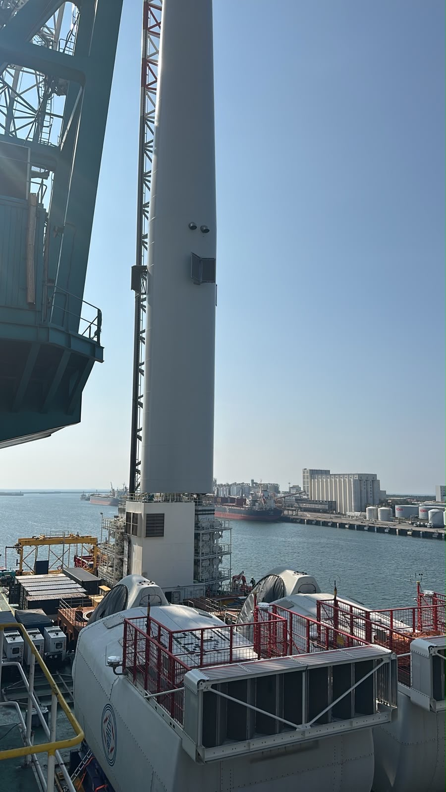
Figure 8 — Tower landing stage. The photograph does not establish completed landing or securing.
The plan must address component mass, centre of gravity, prescribed lifting points, tool engagement, support and stability throughout landing. Engineered supports transfer load to the deck at specified contact points. Voyage securing must resist the assessed transport loads, not just static weight.
Teaching sequence: confirm support readiness → control the suspended section → align the landing interface → transfer weight under the authorised procedure → verify stable support and required securing → release the tool only at the approved hold point.
Keep personnel and hands out of pinch and crush zones. Touching the support does not prove the component is stable, secured or ready for tool release. The lifting supervisor controls the sequence under the approved plan.
9. Nacelles and congested deck handling
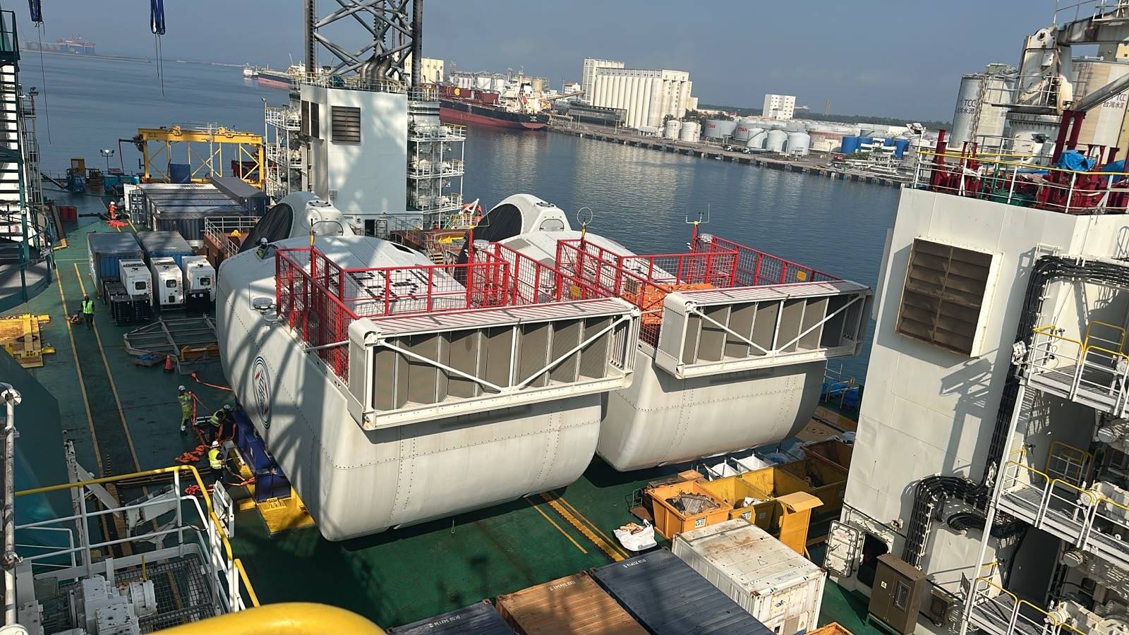
Figure 9 — Nacelles in the deck cargo area. Covers and access platforms are not evidence of approved lift points.
Machinery inside a nacelle means its centre of gravity need not coincide with the visual centre of the cover. Use documented mass, centre of gravity, prescribed lift points and the correct tool. Do not treat guardrails, covers or convenient openings as lifting attachments without explicit approval.
Verify supports, deck loads, sea fastenings and transport restrictions. Preserve safe access around towers, containers, cranes and jacking equipment. Clearances must cover the entire component, tool and rigging through the full path, not just the final position.
10. Lift radius, swept path and clearances
A deck plan locates cargo, supports, cranes, legs and routes; it is only one part of lift planning. Use the current approved revision, crane configuration and operation-specific measurements. The supplied technical drawings are not reproduced here, and their annotations are not adopted as verified dimensions.
Lift radius is generally the horizontal distance from the crane's slewing axis to the vertical load line, subject to the manufacturer's definition. Blade overhang beyond the ship's side is not automatically crane radius. A plan-view circle or a single distance cannot prove lift feasibility.
| Check | Why it matters |
|---|---|
| Radius and configuration at each stage | Capacity may change during pickup, slew and landing |
| Component, tool and rigging envelope | The entire assembly must clear obstructions |
| Vertical clearance | A plan view does not reveal height conflicts |
| Approved movement and deflection allowances | Drawn lines alone do not guarantee real clearance |
| Quay, adjacent vessels and simultaneous work | The lift may extend beyond the immediate deck area |
| Exclusion zones and contingency positions | Personnel and emergency access need protection |
No uploaded drawing dimension is treated as an operational clearance or blade length. Values require approved documents and the responsible engineering assessment.
Master's note
A wind installation vessel changes operating condition several times during one project: cargo carrier, positioning vessel and elevated work platform. Verify who controls each transition, what engineering approval applies, and when the operation must stop. Successful work at one turbine location does not establish seabed suitability at the next.
Self-test
- Which turbine components can you recognise in the port photographs?
Answer 1
Tower sections, nacelles and blades are visible. The photographs illustrate component handling but do not establish weights, model, capacity or securing approval.
- What supports the hull during afloat transit, and what supports it when elevated?
Answer 2
Buoyancy supports the hull afloat. When elevated, the legs transfer hull loads through their feet to the seabed, subject to the jacking system and approved site assessment.
- What is the purpose of preload?
Answer 3
To deliberately apply specified leg loads and assess seabed response and settlement under the approved procedure. It is not a substitute for site-specific geotechnical assessment.
- What is punch-through?
Answer 4
Potentially sudden leg penetration or loss of support associated with seabed conditions, such as stronger soil over weaker material. It can cause uneven support and requires engineering consideration.
- What is air gap, and is there one universal value?
Answer 5
Clearance between the elevated hull underside and the sea surface. Required elevation depends on the site, environmental conditions and vessel structural limits; no universal value applies.
- Does the crane's maximum advertised capacity apply at every working radius?
Answer 6
No. Permitted capacity depends on radius, configuration, load, rigging and applicable limits. Use the crane chart and approved lift plan for the actual lift.
- Does DP support an elevated jack-up hull?
Answer 7
No. DP uses propulsion for afloat positioning where fitted and approved. Elevated support comes from the legs, jacking system and seabed.
- Why are blade lifts sensitive to weather?
Answer 8
Blades have a large exposed area. Wind, gusts and orientation affect load control and forces. Use lift-specific limits, forecasts, communications and stop criteria rather than a generic threshold.
- Does a blade transport rack automatically qualify for lifting with its blade inside?
Answer 9
No. Verify the authorised lifted unit and approved component-specific tool, rigging and attachment points. Transport suitability does not establish lifting approval.
- May a tower lifting tool be released as soon as the tower touches its deck support?
Answer 10
No. Follow the approved hold point after stable support and required securing are verified. Contact alone does not establish stability; keep clear of pinch and crush zones.
- Can the nacelle's centre of gravity and lifting points be identified from its outer cover?
Answer 11
No. Use documented mass and centre of gravity and the prescribed tool and attachments. Covers, guardrails and convenient openings are not lifting points without approval.
- Is blade overhang beyond the ship's side automatically the crane lift radius?
Answer 12
No. Radius is generally measured horizontally from the crane slewing axis to the vertical load line under the maker's definition. Check capacity and the full three-dimensional component, tool and rigging envelope through the lift path.
Official sources and scope
Source review: 6 November 2026. Original introductory text; photographs supplied by Captain Ivan Martsynenko. No vessel-specific operational approval or numerical operating limits are provided.
-
DNV — Jack-up and geotechnical engineering: site-specific assessments, environmental conditions and soil–structure interaction.
-
NOV / GustoMSC — NG-3500X brochure: design-specific jack-up features and preload explanation. Examples are not universal procedures.
-
NOV — Wind turbine installation vessel with telescopic crane delivered to Shimizu: an example of crane configuration linked to sailing and port manoeuvring considerations, not identification of the photographed vessel.
-
DNV-ST-0054 — Transport and installation of wind power plants: structural integrity and planning across wind-component transport and installation.
-
OSHA — Wind turbine custom lifting accessories, interpretation of 8 June 2012: rated-load identification and testing requirements within its US construction scope. This is a supplementary safety reference, not universal shipboard law or certification of the photographed tools.
For actual work, use the vessel's current operating manual, approved site assessment, lifting procedures, component/tool instructions, class conditions and project requirements.