Source and scope
This original lesson uses the supplied “Master & Mates Examination — Part 3: Anchor Handling, Towing, Equipment & Conversions” as a revision checklist. Its filename refers to ARAMCO, but official endorsement, authorship and date have not been verified. It is not official Aramco training. Questions 77–80 are labelled model answers in the supplied document, not verified operator instructions. The uploaded file and its third-party pictures are not redistributed.
Read Part 1 — lights, signals and buoyage and Part 2 — navigation, stability and safety. General guidance and manufacturer sources below were reviewed 7 November 2026. This is revision material, not an anchor deployment, tow hookup, emergency-release or damage-control procedure. Use the approved operation plan, equipment manuals, competent supervision and current vessel/operator requirements.
Anchor parts: recognise the actual design

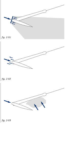
Simplified twin-fluke anatomy. A Danforth-type stock is near the crown; a traditional stocked anchor has a different stock arrangement. Stockless anchors have no stock. Do not transfer attachment-point names between designs.
| Part | Recognition and role |
|---|---|
| Shank | Main member transmitting pull between attachment and anchor body |
| Crown | Region where shank and arms/fluke assembly meet |
| Fluke / palm | Broad surface engaging the seabed; holding behaviour depends on anchor design and soil |
| Arm, shoulder and bill | Terms for supporting/transition regions and fluke tips; terminology varies by design |
| Stock / crossbar | Orienting member on stocked designs; not universally at the top of the shank |
| Eye and connecting shackle | Approved line/chain attachment; distinguish shank attachment from any designated crown or recovery attachment |
Anchor handling lays, recovers or repositions anchors and associated mooring lines using a suitably equipped vessel. Ship anchoring, rig mooring and subsea foundation installation are different operations. Learn the illustrated anchor classes and selection in real conditions; holding capacity is not inferred from an outline drawing or anchor mass alone.
People, control and changing danger zones
The sheet's one officer and two ABs is an unverified example—not universal deck manning. Task complexity, competence, equipment, visibility, fatigue and simultaneous work govern the assessed team. Agree command, bridge/deck/winch responsibilities, communications, stop signals, clear-deck confirmation and what happens if contact is lost.
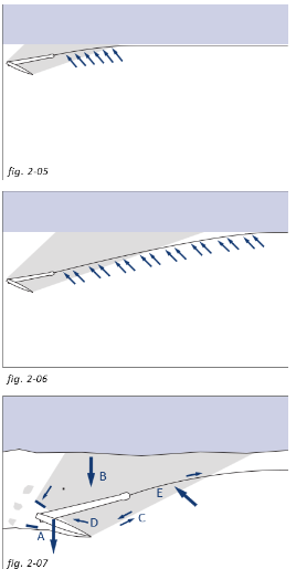
Tensioned wire, chain and rope, suspended anchors, moving winches, tugger leads and loaded connections create crushing, entanglement and recoil hazards. Do not stand in bights or the line of fire. Danger areas move when line leads, vessel heading, loads and failure points change. A painted zone does not make the rest of the deck safe. PPE does not permit exposure to stored energy; use controlled access, suitable barriers and the operation's safe system of work.
Stop and reassess when conditions, line behaviour, equipment status or communications differ from the plan. Do not approach a snagged, unexpectedly tensioned or damaged line to investigate under load.
Tow load path: identify function, not a universal assembly
A planned towing system may include tow attachment structures, bridles, an engineered joining plate, pennants, an approved compliant segment, the main towline, fairleads and towing equipment. Names such as Smit bracket, triangular plate or “monkey face” do not establish suitability or rating. Verify the complete load path, structural attachments, certificates, condition, geometry and approved configuration.
Bollard pull, winch pull, brake holding capacity, line breaking load and equipment WLL/SWL are different quantities. Account for vessel motion, snatch loads, lead angles and system-specific factors. A diameter or material name alone does not establish capacity.
A stretcher can provide compliance in an engineered system; its dimensions, elongation, connections and limits are design-specific. The sheet's description of a wire in parallel as a “fuse” or safe weak link must not be assumed correct. Parallel load sharing, slack/extension and failure sequence need engineering assessment. Do not build a weak link or backup from this diagram or infer controlled release from a smaller diameter.
Chafe protection controls wear only where properly designed and fitted; it does not increase a line's certified strength. Tow pins guide a lead; jaws/stoppers hold only the compatible equipment and load conditions specified by their manufacturer. Neither has an assumed universal operating sequence.
A gog/gob arrangement can constrain the towline lead or influence its effective tow point on some vessels. It does not eliminate girting, where transverse tow force can heel or overturn a tug. Its attachments and release behaviour need assessment. Propulsion, towline geometry, vessel stability and release arrangements remain critical. Never copy the sheet's pin/jaw raising and lowering sequence to another vessel.
Snatch blocks: resultant load is not just line tension

Idealised 180° line reversal with equal tension and no friction/dynamics. The two line-leg forces act together; this is not a block rating or selection calculation.
The block/support reaction is the vector sum of the line-leg forces. In the illustrated idealisation, a line tension of 10 t-force gives about 20 t-force reaction. Other lead angles change the resultant; friction, unequal leg tension and dynamics change the real loads. The sheet's advice to use a snatch block with the same SWL as tugger maximum pull is not sufficient. Check the manufacturer's rating basis, angle factors, connections, support structure, reeving and operational assessment. Crosby's guidance below explains block loading for its covered products.
Do not confuse tonnes of mass with tonnes-force: 1 tonne-force = 9.80665 kN. A diagrammatic force example is not approval to operate at that load.
Equipment recognition and verification
| Equipment family | What to verify before the planned operation |
|---|---|
| Shackles, hooks, plates and slings | Traceable identity, certificate, condition, rated configuration, compatible dimensions and manufacturer-required pin/locking arrangement |
| Pennants, tow wires and terminations | Correct type and construction, documented capacity, end-connection compatibility, inspection status and discard criteria |
| Tugger equipment, snatch blocks and winches | Suitable rating basis, real lead/resultant loads, compatible line/sheave, controls, guards and structural attachment |
| Catchers, messengers, boat hooks and heaving lines | Suitability for the assigned handling task; not substitutes for rated lifting or towing gear |
| Tow pins, stoppers/jaws and release systems | Compatible line/link/socket, operating limits, control location and approved checks |
| Hand tools and consumables | Correct tools for the job, maintained condition, approved fasteners and locking parts; no forcing damaged connections into service |
The supplied fixed inventory, shackle tonnages, 52 mm pennant, 25 t hook and lasso recipe are not universal procurement or rigging specifications. Use the vessel's approved equipment schedule and operation-specific requirements. Wire-rope grips are not automatically approved for a towline or critical lifting termination. Hot-work/cutting equipment needs its own authorisation, isolation and fire/gas precautions; it is not a generic way to release tensioned gear.
See resin socketing fundamentals and socket inspection and removal from service for termination safety and traceability.
Rig-move readiness: questions to settle
- Is the rig/vessel in the correct approved condition for the planned phase, and are all involved parties ready? A jack-up's elevated/preload and afloat tow phases are distinct; do not assume “legs raised and preloaded” describes a single tow-ready condition.
- Are tow/mooring configuration, route, bathymetry, pipelines/cables, field restrictions, weather window, stability and abort arrangements agreed?
- Are gear compatibility, inspection records, structural capacities, control-station changeover, communication and emergency arrangements verified under the actual manuals?
- Are competent personnel, required permissions, contingency resources and the briefing in place, with clear responsibility for authorising each phase?
These are planning questions, not a day-before timetable or hookup sequence. The sheet's 14-day notice, VHF Channel 11, 15-minute waiting time, OIM 1519, MIM/GI numbers and SMS paragraph references are unverified as current requirements. Obtain controlled, current operator copies and verify applicability. Pipeline depressurisation or cable de-energisation is an authorised asset-owner action, never a vessel's assumption.
SMS is the safety management system; the IMO ISM framework requires assessed risks and safeguards. Do not confuse a company's claimed eleven elements with the structure or requirements of the ISM Code. Certificates, flag endorsements, medical fitness, STCW training and task-specific qualifications must match role, vessel, flag and operation; BOSIET/HUET, H₂S and DP certificates are not universal requirements for every seafarer.
Units first: miles, gallons and tons are ambiguous
| Unit | Conversion |
|---|---|
| 1 international foot | Exactly 0.3048 m |
| 1 inch | Exactly 2.54 cm |
| 1 yard | Exactly 0.9144 m |
| 1 metre | About 3.280840 ft or 1.093613 yd |
| 1 nautical mile | Exactly 1852 m; 1 knot = 1 nautical mile/hour |
| 1 international statute mile | Exactly 1609.344 m; not a nautical mile |
| 1 litre | 0.001 m³ = 1000 cm³; not a length |
| 1 US liquid gallon | Exactly 3.785411784 L |
| 1 imperial gallon | Exactly 4.54609 L; not a US gallon |
| 1 petroleum barrel (42 US liquid gallons) | Exactly 158.987294928 L = 0.158987294928 m³ |
| 1 m³ | About 264.172052 US liquid gallons, 6.289811 petroleum barrels or 35.314667 ft³ |
| 1 metric tonne | 1000 kg, about 2204.622622 lb |
| 1 short ton | 2000 lb = 907.18474 kg |
| 1 long ton | 2240 lb = 1016.0469088 kg |
International pound = exactly 0.45359237 kg. Square and cubic conversions use the squared/cubed length factor: 1 in² = 6.4516 cm². A cubic metre is not 35.51 ft³. Identify whether a barrel is the petroleum unit before using its factor.
Small errors still present in the sheet: 18 in = 457.2 mm, not 300 mm; 15 ft = 4.572 m, not an exact 5 m; 10 ft = 3.048 m, not an exact 3 m. Rounded equivalents must not silently alter a specified equipment dimension.
Mass to volume needs density
Volume (m³) = mass (t) ÷ density (t/m³). Then US gallons = m³/0.003785411784; petroleum barrels = m³/0.158987294928. Relative density (“specific gravity”) is dimensionless and needs a stated reference; it is not automatically a certified density in t/m³.
| One-tonne illustration | Assumed density | Volume | US gallons | Petroleum barrels |
|---|---|---|---|---|
| Liquid A | 0.844 t/m³ | 1.184834 m³ | 313.00 | 7.45 |
| Liquid B | 0.800 t/m³ | 1.250000 m³ | 330.22 | 7.86 |
| Liquid C | 1.440 t/m³ | 0.694444 m³ | 183.45 | 4.37 |
These are assumed densities for arithmetic only, not fixed densities of “fuel”, “Safra” or “mud oil”. Verify product identity, measured/certified density and reference temperature; use applicable cargo/tank corrections. Bulk powder volume needs the relevant bulk density, which varies with condition and packing—not a generic solids density or stale table.
For 90 t at an assumed 1.44 t/m³, volume = 62.5 m³; US gallons ≈ 16,510.75, not the sheet's corrected-note value 16,512.3. Conversely 1 m³ at that assumed density has mass 1.44 t. Mass and volume cannot be converted without density, and these arithmetic examples do not authorise filling a tank.
Deck tools and damage-control readiness
A deck toolkit may contain suitable spanners, inspection/cleaning tools, maintained hand tools and approved connection consumables. A damage-control inventory may include approved plugs/wedges, patching materials, shoring and suitable tools. Treat the sheet's quantities as an unverified example, not a statutory minimum or a repair plan.
Keep the actual emergency inventory identified, accessible, maintained and checked against the vessel's damage-control plan. Flooding requires alarm, reporting, safe access/isolation and the planned response. Do not enter a flooding or potentially enclosed space, improvise shoring, or obstruct escape because a box contains timber and cement. Temporary repairs and dewatering need competent assessment of structure, stability and hazards.
Self-test — 12 Questions
- Is an anchor stock always at the top of the shank?
Answer 1
No. Stock location and anchor construction vary. A Danforth-type crossbar is near the crown; stockless anchors have no stock. Identify the actual approved design and attachment points.
- Does “one officer and two ABs” establish universal safe deck manning?
Answer 2
No. Team size and competence follow the assessed task and vessel procedures, with clear command, communication and stop arrangements.
- Is the area outside a painted recoil zone automatically safe?
Answer 3
No. Line-of-fire, bights and moving-equipment hazards change with line leads, loads and vessel movement. Follow the operation's controlled-access arrangements.
- Is a block rated the same as tugger line pull automatically sufficient?
Answer 4
No. The resultant can exceed line tension; an ideal equal-tension 180° reversal at 10 t-force gives about 20 t-force support reaction. Verify geometry, manufacturer rating basis, structure and dynamics.
- Does a gog/gob line eliminate girting?
Answer 5
No. It may influence the towline lead/effective tow point in a particular arrangement, but transverse tow forces, stability and release arrangements still need assessment.
- Can a smaller wire in parallel be assumed to be a safe fuse?
Answer 6
No. Load sharing, extension and failure sequence require engineered verification. Do not infer an approved weak link from diameter or the study sketch.
- Are the document's operator notice periods, channels and manual numbers verified current instructions?
Answer 7
No. Obtain controlled current operator documents and verify applicability. Do not use the unverified examples as operational authority.
- Convert 18 inches to millimetres and 15 feet to metres.
Answer 8
457.2 mm and 4.572 m. The sheet's 300 mm and 5 m are not exact equivalents.
- How do a nautical mile and a statute mile differ?
Answer 9
A nautical mile is 1852 m; an international statute mile is 1609.344 m. A knot is one nautical mile per hour.
- Does one petroleum barrel equal 42 imperial gallons?
Answer 10
No. It is 42 US liquid gallons = 158.987294928 L. An imperial gallon is 4.54609 L; a US liquid gallon is 3.785411784 L.
- At an assumed density of 1.44 t/m³, convert 90 tonnes to volume and US gallons.
Answer 11
90/1.44 = 62.5 m³, approximately 16,510.75 US liquid gallons. The density is an assumption, not a universal product value.
- Does a damage-control box list provide an approved flooding-repair procedure?
Answer 12
No. Follow the vessel's emergency plan and competent assessment; inventory does not authorise unsafe entry, improvised shoring or unassessed repairs.
Official and manufacturer references
- MCA Code of Safe Working Practices, 2026 edition: shipboard safe-work and risk-assessment framework, not an AHTS-specific operation plan.
- MCA MGN 592 Amendment 2 — anchoring, mooring, towing or hauling equipment: equipment, training, line and stored-energy hazards; UK guidance with its own scope.
- Crosby snatch-block application and operation information and tackle-block loading examples: resultant loads and rating considerations for covered products; consult the actual installed equipment manufacturer.
- IMO ISM Code: safety management, assessed risks and safeguards.
- NIST Guide to SI — conversion factors: unit definitions and conversions; correct units do not validate a loading assumption.