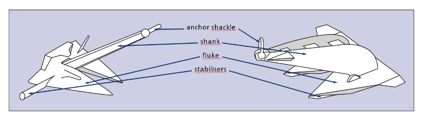
Source and scope: Original teaching notes informed by Vryhof Anchors B.V., Anchor Manual 2010 — The Guide to Anchoring, especially pages 6–12 and 25–50. Source reviewed 7 November 2026. Only the first 50 pages of the uploaded manual were extracted; this is not a review of the complete book. The manual is a manufacturer reference from 2010, not current class rules or an approved operating procedure. The full manual and product performance charts are not redistributed. The illustrated classification below uses the separately supplied anchor drawings with attribution.
Learning objectives
Explain how a mooring transfers vessel loads to the seabed; distinguish anchor families; identify why soil, line geometry and installation affect holding capacity; distinguish factory proof testing from site holding evidence; recognise anchor-handling hazards.
Offshore mooring is a complete system
Wind, waves and current act on a floating unit. The resulting loads pass through fairleads, mooring lines and connectors into foundations and the surrounding seabed. Anchor mass alone does not describe that load path or its capacity. A suitable anchor cannot compensate for an unsuitable connector, damaged line or inadequate site assessment.
| Arrangement | Concept | Operational point |
|---|---|---|
| Spread mooring | Multiple lines hold a unit around its operating position | Assess the complete layout and load redistribution, not one anchor in isolation |
| CALM buoy | Several seabed moorings support a buoy; the receiving vessel can weathervane around it | Vessel connection and buoy mooring are different parts of the system |
| Turret mooring | Lines converge at a turret on an FPSO/FSO | The hull can rotate relative to the mooring arrangement |
| Catenary mooring | A curved line may have a seabed-contact segment | Touchdown and line–soil interaction affect the load reaching the anchor |
| Taut or semi-taut mooring | Lines can reach the foundation at an appreciable angle | Select a foundation designed and qualified for the relevant inclined loads |
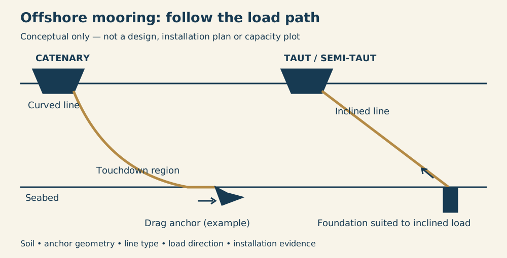
Original educational diagram; not to scale. The foundation symbols are examples, not installation recommendations.
Anchor families
| Type | How resistance is developed | What must be checked |
|---|---|---|
| Deadweight | Submerged weight and interaction with the seabed | Sliding, uplift and actual seabed conditions |
| Drag-embedment | Flukes penetrate and mobilise soil as load is applied | Soil profile, geometry, drag corridor and permitted load direction |
| Driven pile | Soil resistance along and around a pile | Geotechnical design, axial/lateral loading and installation records |
| Suction foundation | A caisson is installed using controlled pressure difference; the installed foundation mobilises soil resistance | Suitable soil, installation controls and design loading |
| Plate / vertically loaded anchor | An embedded plate mobilises soil under its intended loading orientation | Embedment, orientation and model-specific qualification |
A suction foundation does not simply rely on an installation pump running continuously to hold a vessel. Installation and in-service foundation resistance are different engineering questions.
Illustrated anchor classes A–G
These are all seven classes in the supplied Vryhof classification, not every anchor or seabed-foundation type in existence. The letters group anchors by geometry and historical holding efficiency; they are not classification-society approval grades, nor a substitute for HHP/SHHP certification. Driven piles, suction caissons and deadweights belong to the broader foundation families described above, rather than this illustrated A–G scheme.
Source: Vryhof Anchors B.V., Anchor Manual 2010 — The Guide to Anchoring, supplied excerpts headed “Characteristics of anchor types”, printed pages 14–20. Drawings reproduced from the supplied excerpts; comments are original teaching summaries. Product names follow the source's historical labels, not a claim about current availability or approval.
Class A — slender, deeply penetrating anchors
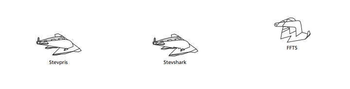
- Stevpris: a slender shank and broad fluke form a drag-embedment anchor; penetration and the site soil govern performance.
- Stevshark: another slender, deeply penetrating design in this group; the exact model and seabed conditions matter more than its class letter.
- FFTS: a differently shaped fluke/shank arrangement in the same historical penetration group; use model-specific installation evidence rather than visual similarity.
Class B — elbowed shank
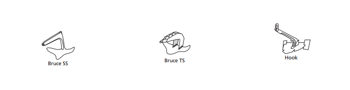
- Bruce SS: the bent or “elbowed” shank is the defining feature; the source associates this geometry with improved penetration.
- Bruce TS: a related elbowed-shank form with a different fluke profile; do not transfer holding data between SS and TS without evidence.
- Hook: combines a pronounced shank bend with its own fluke arrangement; assess embedment and loading direction for the actual anchor.
Class C — short shank and central crown hinge
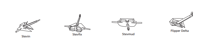
- Stevin: a relatively short shank and stabilising geometry place it in the central-hinge group; stability during setting is important.
- Stevfix: uses a compact fluke-and-shank form with stabilisers; confirm the actual arrangement rather than assuming all Class C anchors behave identically.
- Stevmud: the broad fluke profile is readily visible; its name alone is not proof of suitability for a particular mud or clay deposit.
- Flipper Delta: its distinctive fluke and stabilising form belong to this historical group; load direction and penetration remain model-specific.
Class D — rear hinge, longer shank and stabilisers
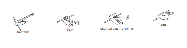
- Danforth: long-shank, paired-fluke form with a transverse stabilising stock; reliable setting depends on penetration and suitable ground.
- LWT: a lightweight-style fluke anchor shown with a long shank and rear stabilising arrangement; “lightweight” does not establish a safe holding load.
- Moorfast / Stato / Offdrill: the source places these names beside one representative drawing; treat them as a grouped historical illustration, not necessarily identical products.
- Boss: a compact fluke arrangement included in Class D; the shape shown is an identification aid, not a performance certificate.
Class E — short, thick stabilisers and rear hinge
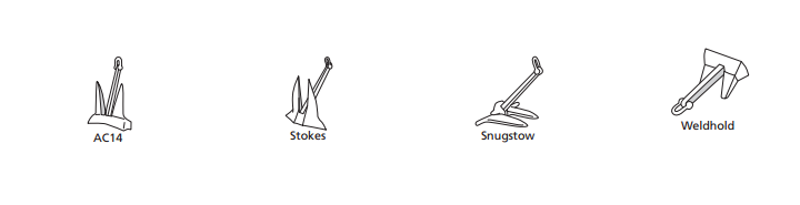
- AC14: a compact stockless-style anchor with broad flukes; HHP approval must be confirmed for the actual certified anchor, not inferred from the name.
- Stokes: its flukes and compact crown form provide the visual identifier; compare its certificate and condition with the intended service.
- Snugstow: a low-profile form in this group; stowage compatibility does not by itself demonstrate seabed holding capacity.
- Weldhold: a broad-faced fluke arrangement with a short shank; structural condition and documented model limits still govern use.
Class F — stockless, crown-stabilised anchors
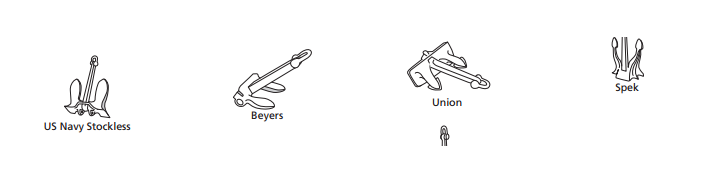
- US Navy Stockless: no transverse stock; the crown and fluke assembly provide the stabilising geometry described by the source.
- Beyers: another stockless form with a distinct crown profile; setting and holding depend on the anchor–soil interaction.
- Union: a stockless arrangement shown with a substantial crown; weight alone cannot be converted into guaranteed holding.
- Spek: an elongated stockless form in the same group; verify its actual geometry, certification and wear before identifying it in service.
Class G — smaller fluke area and forward stock/stabilisation
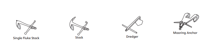
- Single Fluke Stock: one main fluke with a transverse stock; orientation and intended load direction are especially important to identification and use.
- Stock: the familiar stocked form has relatively small flukes compared with modern broad-fluke drag anchors; a stock helps establish the setting attitude.
- Dredger: an angular fluke form labelled for dredging service in the source; the label is not an offshore-mooring approval.
- Mooring Anchor: the source's final example is a specialised stocked mooring form; “mooring anchor” here is a pictured type, not the name of every permanent foundation.
Historical efficiency ranges — not working loads
The supplied pages give the following approximate holding-capacity-to-anchor-weight ratios for a 10-tonne anchor. These are the manufacturer's historical comparison ranges under its source assumptions, not guaranteed values, safety factors, modern class thresholds or approved working limits. Overlapping ranges also show why the letters are not a universal ranking for every soil.
| Vryhof historical class | Source's indicative efficiency range |
|---|---|
| A | 33–55 |
| B | 17–25 |
| C | 14–26 |
| D | 8–15 |
| E | 8–11 |
| F | 4–6 |
| G | Less than 6 |
Do not multiply anchor weight by this table to select a mooring or set a winch load. Current model documentation, applicable class requirements, geotechnical investigation, installation records and an approved mooring analysis are required.
Shape, soil flow and penetration
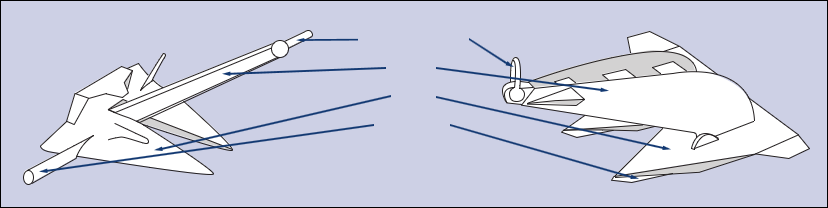
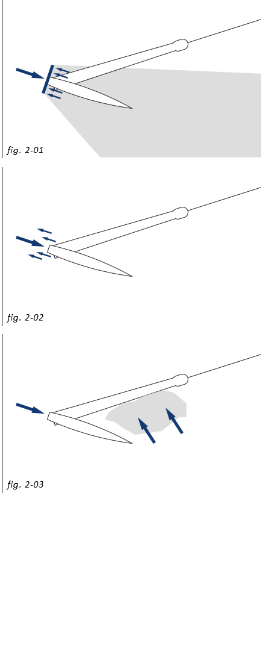
The supplied illustration draws attention to how fluke and shank shape interact with material passing around the anchor during penetration. It is a qualitative geometry comparison, not a measured holding-capacity plot; the unlabelled drawing does not establish model names, force magnitudes or a universally superior design.
Why equal-weight anchors can hold differently
Vryhof's theory discussion highlights fluke area, shank geometry, penetration, soil, mooring-line type and applied load. Two anchors of equal mass can have very different performance. Product comparisons and holding-to-weight ratios are conditional test results, not universal multipliers.
- Soil profile: sand, clay, layered ground and hard obstructions affect penetration and resistance differently. A charted seabed description is not a substitute for project geotechnical data.
- Geometry: fluke area and structural strength matter together. A larger area is not automatically a safe increase in capacity.
- Penetration: soft clay may allow deeper embedment but does not automatically provide greater holding than denser or stronger soil.
- Line–soil interaction: buried chain or wire can change the direction and magnitude of the load at the anchor.
- Load direction: horizontal, inclined, lateral and cyclic loading must be considered within the specific design envelope.
Uplift: do not generalise a test result
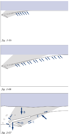
Conventional drag anchors and specialised vertically loaded anchors must not be treated as interchangeable. The manual reports inclined-load behaviour for particular deeply embedded anchors and soils. Those examples do not authorise an uplift angle for every drag anchor. Mudline angle and the angle at a buried shackle need not be identical because the buried line curves through soil. Use the actual model's current limits and the approved site analysis.
Loads and evidence: four different questions
| Term | Meaning for the learner |
|---|---|
| Ultimate holding capacity | Resistance associated with a defined soil/anchor/loading condition; not a routine working limit |
| Design load | Demand calculated for the specified environment and operating or failure condition |
| Factory proof load | Structural test evidence for the anchor or component; not proof of seabed holding at a particular site |
| Installation tension / pretension | A controlled site activity and recorded load, assessed against approved acceptance criteria |
The 2010 manual contains safety-factor tables and product-specific tests. They are intentionally not adopted here as present-day design values. Applicable class requirements, current manufacturer documents, environmental criteria and the project mooring analysis govern acceptance. Consider intact and specified damaged conditions: loss of one line can redistribute loads onto the remaining system.
Installation and retrieval: the officer's questions
Before work, confirm an approved plan, anchor/line identification, certificates, soil and route information, subsea exclusion areas, equipment capacities and operational limits. Agree communications, stop criteria and roles between the offshore unit, anchor-handling vessel and deck team.
During work, record the planned position, actual deployment and applicable tension/drag observations. Unexpected movement, abnormal loads, loss of communication or disagreement with the plan require the agreed stop-and-assess response—not improvised increases in winch power.
Retrieval can create high breakout forces, bending and snagging loads. An anchor caught on a rack, stern roller or incompatible handling device can be damaged even when its in-service holding performance was satisfactory.
Safety boundary: Keep personnel clear of bights, loaded lines and potential recoil paths. Vessel stability, stern loading, towing-pin/shark-jaw compatibility and subsea obstructions need operation-specific assessment. This lesson gives no generic winch settings, fluke-angle changes, breakout sequence or safe-working load. Use competent supervision, the vessel SMS and the approved procedure.
Master's note
Ask: “What is the evidence that this whole mooring system will hold at this site, in this loading condition?” Anchor weight, a factory certificate and the installation tension each answer only part of that question.
Practical follow-on lesson
Choosing and Using Anchor Classes in Real Conditions — compare Classes A–G against seabed, changing pull, setting evidence and handling limits.
Sources and further study
- Vryhof Anchors B.V., Anchor Manual 2010 — The Guide to Anchoring, uploaded source; pages 6–12, 25–28, 29, 34–40 and 46–50 informed these original notes; separately supplied printed pages 14–20 support the illustrated Classes A–G section. Historical manufacturer guidance; remaining pages not reviewed.
- Vryhof website — manufacturer address printed in the manual; current documents and product limits should be obtained from the manufacturer. Link destination not independently verified in this review.
- Bollard Pull Test Procedure — vessel pulling performance is not the same as installed anchor capacity.
- Dynamic Positioning Fundamentals — contrast thruster-based station keeping with seabed mooring.
- Turnbuckles and Rigging Inspection — component traceability and condition.
Case study: worn mooring lines part in a gale (Endurance, Bremerhaven 2021)
On 13 March 2021 the car carrier Endurance was moored starboard side to in Bremerhaven when offshore gusts reached about 50 knots. The master was already on the bridge, had called for tugs and sent officers to check the lines. At about 0945 the lines parted. The master ordered the starboard anchor let go, the main engine started and the ramp raised, and sounded the general alarm. The first tugs arrived about eight minutes later but could not stop the ship drifting across the basin into a dry dock and two pontoons. Nobody was hurt and there was no pollution; the ship was made fast at a sheltered berth almost four hours later.
The German investigator (BSU) found the main cause was worn lines that had not been replaced in time, because the safety management system had no suitable procedure.
Lessons for the deck officer:
- Since 1 January 2024, SOLAS II-1/3-8 and the IMO guidelines (MSC.1/Circ.1619 and 1620) require ship-specific procedures for mooring operations and for inspecting, maintaining and replacing mooring equipment, including lines. Wear must be found and recorded before it causes a failure.
- Heavy weather at berth is a planned event: watch the forecast, add lines, order tugs early and keep the engine and an anchor ready.
- A high-sided car carrier has a very large wind area, so it drifts quickly once lines go.
- Stand clear of snap-back zones while lines are under high load.
Source: IIMS News Bulletin, July 2025, summarising the BSU report.
Self-test
- Does a heavier anchor always provide more holding capacity than a lighter one?
Answer 1
No. Geometry, fluke area, soil, penetration, line interaction and load direction affect performance; mass alone is insufficient.
- What is the key load-path difference between a catenary and a taut mooring?
Answer 2
A catenary line is curved and may contact the seabed; a taut line can apply a substantial inclined load at its foundation. Actual foundation loads require analysis.
- Does a factory proof-load certificate prove that an anchor will hold at the chosen offshore site?
Answer 3
No. It is structural test evidence. Site holding depends on soil, installation and the intended load conditions.
- Why must a published uplift test not be used as a universal drag-anchor limit?
Answer 4
The result belongs to a particular anchor, soil, embedment and loading arrangement. Only qualified model-specific limits and approved analysis apply.
- Why is soft clay not automatically better holding ground?
Answer 5
It may allow deep penetration, but soil strength and other conditions still determine resistance. Penetration depth alone is not capacity.
- What happens to the other mooring lines when one line fails?
Answer 6
Loads can redistribute and vessel offset can change. The specified damaged condition must be assessed for the system.
- Name two retrieval hazards that can damage an anchor.
Answer 7
High soil breakout forces and snagging at the rack or stern roller; incompatible handling devices and lateral loads are further examples.
- Which documents govern a real anchor-handling operation instead of this lesson?
Answer 8
The approved project plan and mooring analysis, applicable class requirements, current manufacturer limits, vessel SMS and operation-specific risk assessment.